
What Is a Buttress Thread: One-Way Power Transmission, and Why Metric and American Are Two Systems
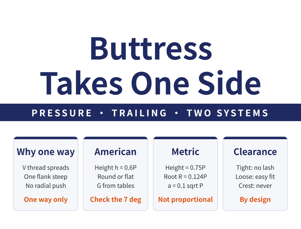
A symmetrical V thread pushes the nut open, because both flanks generate a radial force component. A buttress thread makes one flank nearly vertical, so that force almost disappears - which is why jacks, presses and injection-mould clamping all use it. But two entirely different systems are both called buttress: the American one is 7 degrees / 45 degrees, the metric one is 3 degrees / 30 degrees, and their heights, clearances and root radii all differ.
1. What a buttress thread is for
A symmetrical V thread has two flanks at the same angle. When it transmits load, each flank produces a radial force component, and together they push the nut outwards. Power transmission threads have large pitches and carry large loads, so that opening becomes a real problem.
The buttress thread solves it by making the two flanks asymmetric: one flank is nearly vertical and carries the whole load; the other is at a large angle and only serves chip clearance and ease of manufacture.
| Flank | Angle | What it does |
|---|---|---|
| Pressure flank | 7° American, 3° metric | Near vertical, almost no radial component |
| Trailing flank | 45° American, 30° metric | Chip clearance and machinability, carries nothing |
So it is a one-way power transmission thread: jacks, presses and injection-mould clamping all work this way. Fitted the wrong way round it is worse than useless - the load then sits on the 45 or 30 degree flank, and the radial component is larger than a symmetrical V thread would give.
2. Three common buttress forms, and why the angle order misleads
| System | Angles as written | Which one is loaded |
|---|---|---|
| American Buttress | 7° / 45° | The first one, 7° |
| English Buttress | 7° / 45° | Same |
| Metric buttress thread | 3° / 30° | The first one, 3° |
| Saw-tooth thread DIN 513 | 30° / 3° | The second one, 3° (order reversed) |
The rule: when you see two angles, ask which flank is loaded, do not read them in written order. DIN 513 and the metric buttress thread use the same pair of angles, written the other way round. Read them in order and you will take 30 degrees as the pressure flank, and every load-direction judgement after that is wrong.
3. The metric system: nine formulas
d is the nominal size (major diameter) and P is the pitch.
| Symbol | Name | Formula |
|---|---|---|
| H1 | Basic thread height | 0.75 P |
| h3 | External thread depth | H1 + ac = 0.867 77 P |
| a | Axial clearance | 0.1 √P (see section 4) |
| ac | Radial increment | 0.117 77 P |
| w | Crest width | 0.263 84 P |
| e | Root width | w − a |
| R | Root radius | 0.124 27 P |
| D1 | Internal minor diameter | d − 2 H1 = d − 1.5 P |
| d3 | External minor diameter | d − 2 h3 |
| d2 = D2 | Pitch diameter | d − 0.75 P |
4. Axial clearance is the only term that is not proportional
Every other term above is a coefficient times P. Only the axial clearance a is 0.1 √P. That means clearance does not grow in proportion when the pitch grows.
| Pitch P | Axial clearance a | Share of P |
|---|---|---|
| 2 mm | 0.141 mm | 7.1% |
| 8 mm | 0.283 mm | 3.5% |
| 32 mm | 0.566 mm | 1.8% |
A coarse pitch is relatively tighter. That is deliberate: the clearance exists to absorb manufacturing error and coating thickness, and neither of those scales with pitch. Treat a as a proportion and extrapolate, and a coarse pitch comes out with far too much clearance.
5. Which side keeps the clearance is a design choice
| System | Where the clearance sits | Trade-off |
|---|---|---|
| Pressure flank in contact | Minor diameter and trailing flank only | No axial lost motion; suits positioning accuracy or reversing loads |
| Internal thread system | Minor diameter and both flanks | Easy to assemble, tolerant; lost motion on reversal |
What the two share matters more than how they differ: neither leaves clearance at the major diameter. The only question is whether the pressure flank sits tight. A drawing marked as the internal thread system is the one with clearance on both flanks.
⚠ For the internal thread system, the crest truncation of the external thread is written as s = 0.3149 A0, where A0 is the basic allowance on the external pitch diameter. A0 is a table value and no figure is given for it in this section, so this expression yields no number - that is a limit of this section, not a choice made here.
6. The American system: two root forms
The American buttress thread has a basic thread height of h = 0.6 P, not the metric 0.75 P. The height of the fully extended sharp V follows from the tangents of the two flank angles:
H = P ÷ (tan 7° + tan 45°) = P ÷ 1.122785 = 0.890 64 P
| Form | Basic thread height | How the root closes |
|---|---|---|
| Rounded root | h = 0.6 P | Radius about 0.020 P; better fatigue life |
| Flat root | h = 0.6 P | Flat width S = 0.092 8 P; easier to machine |
The basic height is identical; only the root differs. Choose by whether the part sees alternating load or whether machining cost dominates.
7. Calculating the American diameters
D is the basic major diameter, G the allowance and p the pitch. The table below is the maximum material condition, that is the basic size column.
| Symbol | Name | Basic size |
|---|---|---|
| Dn | Internal major diameter | D + 0.125 42 p |
| Ds | External major diameter | D − G |
| En | Internal pitch diameter | D − h |
| Es | External pitch diameter | D − h − G |
| Ks | External minor diameter | D − 1.325 42 p − G |
| Kn | Internal minor diameter | D − 2h |
| hn = hs | Thread height, internal and external | 0.662 71 p |
| he | Depth of engagement | h − 0.5 G |
The coefficients hold together: 1.325 42 = 2h + 0.125 42, so the external minor diameter sits one internal-major-diameter increment below the internal minor diameter, and the two give up clearance symmetrically.
⚠ Two limits to state first. One: G, the allowance, and the individual tolerances are not given values here, so any expression containing G produces no number until the allowance and tolerance tables are consulted. Two: the subscript on the internal minor diameter Kn in the minimum material condition column is doubtful - it is marked as minimum, yet the internal major and pitch diameters in the same column are marked maximum and all three expressions move the same way. It is reproduced here unchanged, and anyone using that cell should check it against supplier catalogues, standards or their own measurement.
8. Getting the allowance G and the pitch-diameter tolerance
Two values in the formulas above, the allowance G and the pitch-diameter tolerance, come from a table. That table can be calculated: the class 2 pitch-diameter tolerance is a diameter increment plus a pitch increment:
Class 2 pitch-diameter tolerance = 0.002 × ∛D + 0.0173 × √p
(D = major diameter, p = pitch, both in inches)
The three classes hold a fixed relation to each other: class 1 is about 1.5 times class 2, class 3 about two thirds of it, and the external allowance G matches the class 3 pitch-diameter tolerance cell for cell — the same G is applied to the major, pitch and minor diameters of the external thread. ⚠ That set of ratios is a pattern read off the three tables, not a clause written in the standard. Use it to estimate a combination the table does not list; for acceptance, use the value from the standard.
One worked case: 2 in major diameter, 8 threads per inch
Pitch p = 1/8 = 0.125 in
Diameter increment = 0.002 × ∛2 = 0.00252
Pitch increment = 0.0173 × √0.125 = 0.00612
Class 2 pitch-diameter tolerance ≈ 0.0086 in, with an allowance G of 0.0058 in
Put G back into the formulas above and, at the tightest, the internal and external pitch diameters still leave 0.0058 in between them — the allowance is that guaranteed gap.
⚠ The underlying figures come from a 1957 edition. The thread form has not changed, but whether the tolerances and allowances were revised cannot be judged from them: for actual machining and acceptance, follow the current ASME B1.9.
9. Choosing between the two systems
| Item | Metric | American standard |
|---|---|---|
| Flank angles | 3° / 30° | 7° / 45° |
| Basic thread height | H1 = 0.75 P | h = 0.6 P |
| External thread depth | 0.867 77 P | 0.662 71 P |
| Root radius | 0.124 27 P | 0.071 41 P (theoretical) |
| How clearance is expressed | Axial clearance a = 0.1 √P | Allowance G, from tables |
A 3 degree pressure flank is closer to vertical than a 7 degree one, so the radial component is smaller and transmission is more efficient; the price is sharper stress concentration at the root. That is why the metric root radius is nearly twice the American one. They are different trade-offs, not a ranking.
10. FAQ
Q: Can a buttress thread carry load in both directions?
No. One-way loading is the premise of the design. Only a nearly vertical pressure flank - 7 degrees American, 3 degrees metric - keeps the radial component near zero. Load it the other way and the force sits on the 45 or 30 degree trailing flank, where the radial component exceeds that of a symmetrical V thread. Use a trapezoidal or square thread when you need both directions.
Q: Are 30/3 and 3/30 two different threads?
No, the same pair of angles written in opposite order. DIN 513 is usually written 30 / 3, and metric buttress data is usually written 3 / 30. The 3 degree flank is the loaded one in both. Do not judge by the order; ask which angle is closer to vertical, because that is the face carrying the load.
Q: Why is axial clearance a square root rather than a proportion?
Because the clearance has to absorb manufacturing error and coating thickness, and neither scales with pitch. With a = 0.1 root P, the clearance share falls as the pitch rises: 7.1 percent at P = 2 mm, only 1.8 percent at P = 32 mm. Treat it as a proportion and extrapolate to a coarse pitch, and the result is far too much clearance.
Q: Rounded root or flat root?
Both have the same basic thread height; only the root closure differs. The rounded form has better fatigue life and suits parts under alternating load, while the flat form is easier to machine. For the American system the radius is about 0.020 P and the flat is about 0.092 8 P. The metric root radius R = 0.124 27 P is nearly twice the American figure, because its pressure flank is closer to vertical and root stress concentration is sharper.
For the full comparison of thread forms see Thread Profile Guide: 60° V, 55° Whitworth, Trapezoidal & Round; for the standards and designations of each system see Thread Types Guide: Internal/External, Profiles & Standards; and for infeed when turning a coarse one-way thread see Thread Infeed Methods Explained: Radial vs Flank Infeed & Wiper Edge.
Published: 2026-09-19 | Last updated: 2026-09-24









