Hole Tolerance Chart: H7, H8, H9 & G6 Values (ISO 286)
The hole tolerance chart is one of the core standards in mechanical design and CNC machining. Grades such as H, G and F define the allowed size range of a hole, ensuring fit accuracy and assembly stability. This guide covers common hole tolerance grades, code structure, size ranges and fit applications (clearance, transition, interference), with full tolerance reference images to help engineers pick the right fit.
1. What Hole Tolerance Is
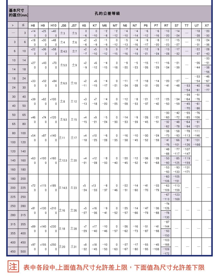
Hole tolerance is the allowed variation of a hole's actual size, given as an upper limit (max) and lower limit (min). In the chart, the top value is the upper limit and the bottom value the lower limit.
H7 is a hole tolerance under ISO 286; for shaft designations such as h7, g6 or f7 see the Shaft Tolerance Chart.
2. Code Structure
A hole tolerance code is a letter (position) plus a number (precision):
| Letter (position) | Meaning |
|---|---|
| H | Datum hole (lower limit 0, most common) |
| G, F (E, D…) | Hole larger than nominal (positive lower deviation); clearance fit with a datum h shaft |
| J, JS, K, M, N | Transition fit with an h6 shaft (clearance or interference) |
| P onward (R, S…) | Interference fit with an h6 shaft |
The number is the IT grade: smaller number, higher precision, tighter band. E.g. H7 for precision fits; H8 and H9 are general machining grades.

3. Common Hole Tolerance (H Series) Example
The H series is the most common standard; the lower limit is normally 0. For the Ø10 mm range (reference values; use the chart image below for exact figures):
| Grade | Ø10 tolerance (ref.) | Positioning |
|---|---|---|
| H7 | approx. +15 / 0 μm | Precision machining |
| H8 | approx. +22 / 0 μm | General machining |
| H9 | approx. +36 / 0 μm | General machining (wider band) |
This means the hole only ever exceeds the nominal size, never falls below it.
4. Other Bands (G, F, E Series)
G, F and E are clearance-fit letters under ISO/JIS: their lower deviation is positive, so the hole is always larger than nominal. H has a lower deviation of exactly 0, while G, F and E sit progressively further above the zero line — for the >6–10 mm range, G6 is +14/+5, F7 is +28/+13 and E8 is +47/+25 μm (ISO 286). With the same datum h shaft, clearance therefore grows from G to F to E. None of these letters is for interference or press fits; for interference look at P onward (see Section 2).
5. Fit Types and Applications
A hole tolerance only tells you the fit once it is paired with a shaft tolerance: clearance, transition or interference; section 2 already sorts the letters roughly by type. The definitions, common combinations and a worked φ25 example with actual limits are gathered in section 4 of ISO Fits Explained. One thing to keep in mind: the same code can land in a different fit type in a different size range (H7/p6 at 3 mm and below, for example, can open up a clearance), so always judge a fit together with its size range.
6. Size Range vs Tolerance
Tolerance widens with size: Ø3 mm tiny, Ø100 mm noticeably larger, Ø500 mm larger still — because machining and measurement error grow with size.
7. CNC Selection Guide
To pick the hole and shaft codes from what the joint has to do (slide, locate or be pressed in), see sections 5 to 7 of ISO Fits Explained: based on the application examples in JIS B 0401, they list the shafts paired with an H7 hole from loose to tight and mark where parts become hard to dismantle without damage.
For matching shaft tolerances see the Shaft Tolerance Chart.
Hole is within H7 but the shaft still will not go in? The hole’s position or perpendicularity may be off — see the Geometric Tolerance Symbols Chart.
Thread tolerances are a separate system: they control pitch and minor diameters rather than hole or shaft sizes — see the Metric Thread Tolerance Chart.
FAQ
Q: What is the H7 hole tolerance?
H7 is a datum hole: lower limit fixed at 0, positive deviation only, growing with the size range. In the over 6 up to 10 mm range H7 = +15/0 μm (ISO 286). Ø10 falls in that range; anything over 10 (e.g. Ø10.5) moves to the over 10 up to 14 mm range at +18/0 μm, so find the range first.
Q: Why is the H series lower limit always 0?
H is the datum hole, defined so the lower limit equals nominal (deviation 0), so the hole is only ever larger. This makes it an easy fit datum, with the shaft tolerance setting clearance or interference.
Q: Does hole tolerance change with size?
Yes. At the same grade, the larger the size the wider the band, because machining and measurement error grow with size. Always match the correct size range before reading the limits.
Q: Which tolerance for a bearing bore?
For bearings it depends on which ring rotates: the ring carrying the rotating load gets an interference fit, the ring carrying the stationary load a clearance fit (e.g. when the inner ring turns with the shaft, the outer ring is a clearance fit in the housing bore). Take the exact tolerance codes from the bearing maker's catalog and select them together with the shaft tolerance.
For the full reading guide on this topic, see Hole Accuracy: A Complete Reading Guide.
Published: 2026-03-25 | Last updated: 2026-10-21