Metric Thread Tolerance Chart|M1–M48 Pitch, Minor Dia & Tolerance
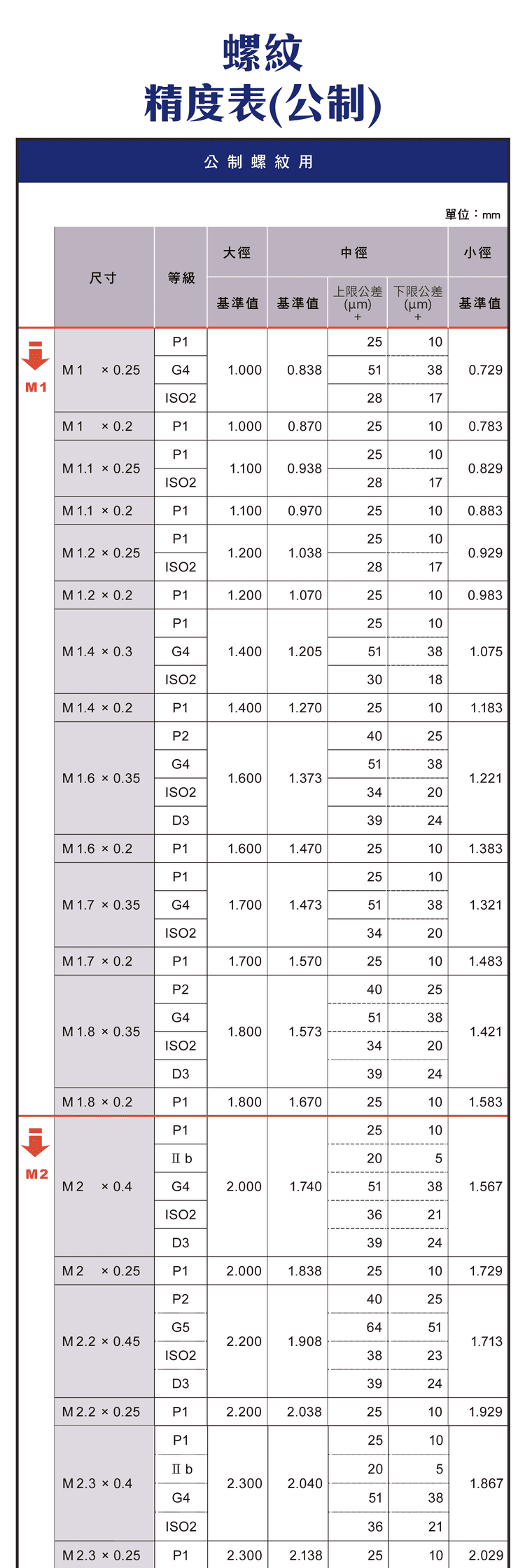
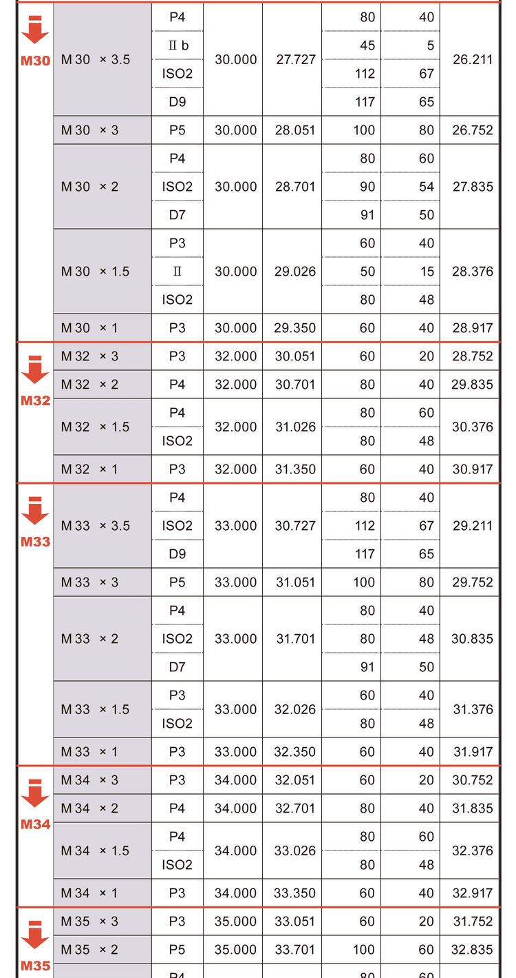
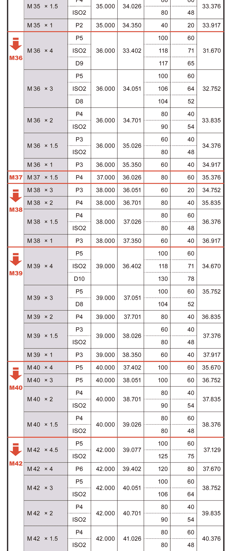
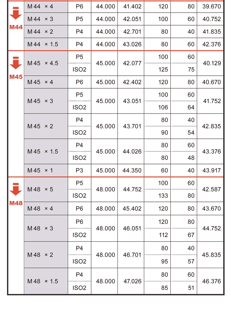
The metric thread tolerance chart is a key reference for machining, tapping and quality inspection. It covers the major, pitch and minor diameters of M1–M48 plus tolerance ranges for grades such as P1, P2, 6G and ISO. Use it to match tap-drill (pilot-hole) size, thread-fit accuracy and inspection standards, reducing bad threads, poor engagement and dimensional error — ideal for CNC machining, precision parts and QC.
1. The Three Core Diameters
Metric threads are defined by three basic diameters, matched to precision grades for different needs:
| Diameter | Description |
|---|---|
| Major diameter | Largest (nominal) thread diameter |
| Pitch diameter | Key size that sets fit accuracy and tightness |
| Minor diameter | Root diameter; affects strength and is close to the tap-drill size |
2. Basic Sizes for Common Threads (ISO 724)
The table below gives basic sizes for common metric coarse threads (per ISO 724: pitch dia = major − 0.6495×pitch; internal basic minor = major − 1.0825×pitch), a quick reference for pilot holes. For the full M1–M48 set and all tolerance grades, refer to the original chart images below.
| Size | Pitch P(mm) | Major(mm) | Pitch dia(mm) | Minor(mm) | Tap drill(mm) |
|---|---|---|---|---|---|
| M3 | 0.5 | 3.000 | 2.675 | 2.459 | 2.5 |
| M4 | 0.7 | 4.000 | 3.545 | 3.242 | 3.3 |
| M5 | 0.8 | 5.000 | 4.480 | 4.134 | 4.2 |
| M6 | 1.0 | 6.000 | 5.350 | 4.917 | 5.0 |
| M8 | 1.25 | 8.000 | 7.188 | 6.647 | 6.8 |
| M10 | 1.5 | 10.000 | 9.026 | 8.376 | 8.5 |
| M12 | 1.75 | 12.000 | 10.863 | 10.106 | 10.2 |
※ ISO 724 basic-size example (coarse); tap-drill values are common references — adjust for material and tap type. See the Metric Tap Drill Size Chart Guide.
3. Precision Grades
| Grade | Traits and use |
|---|---|
| P1 | Lowest tolerance-zone position: smallest tapped thread, tightest fit; precision parts needing a close fit |
| P2 | Zone one step higher than P1, looser fit; general machining and assembly |
| G grade (6G, 7G) | ISO tolerance system; international specs and export parts |
| ISO grade | International standard fit; cross-border, unified specs |
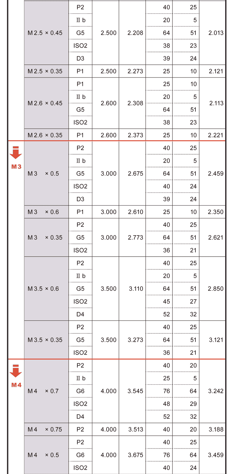
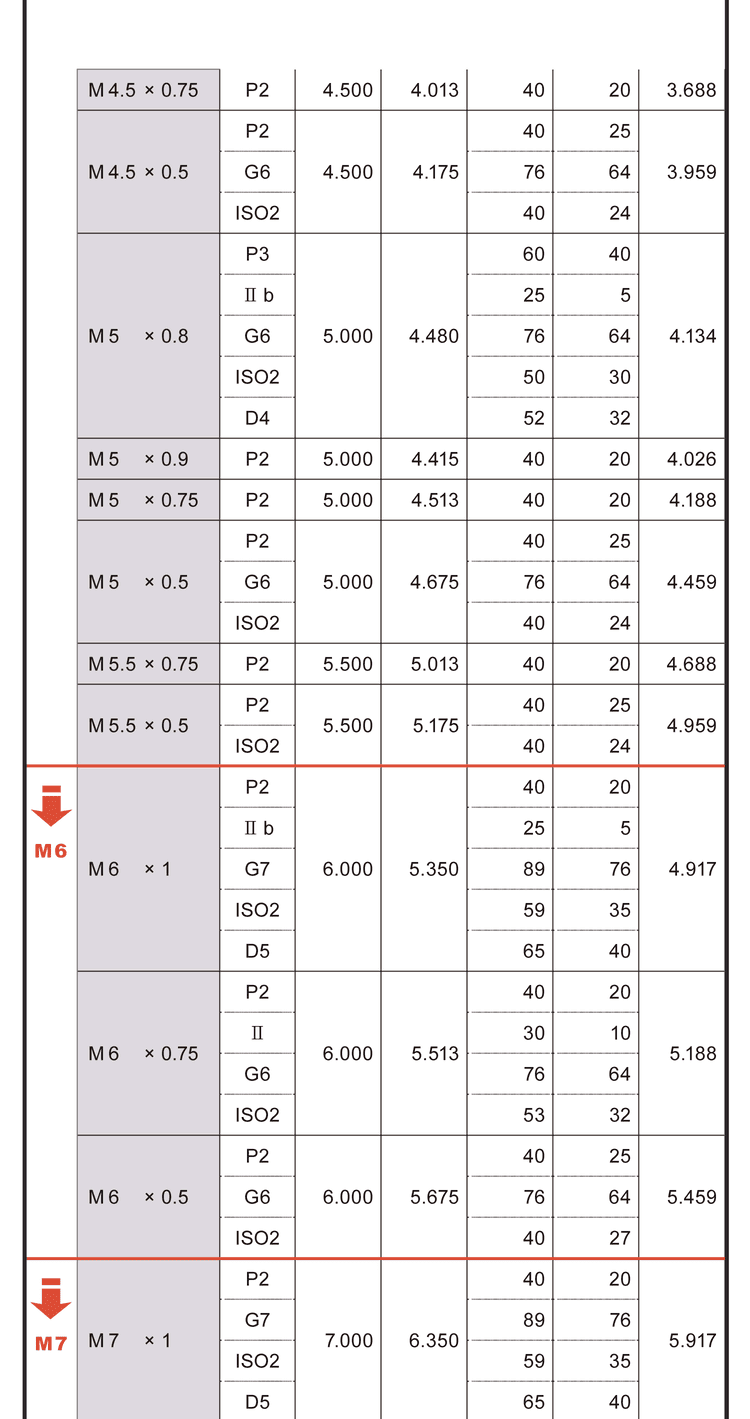
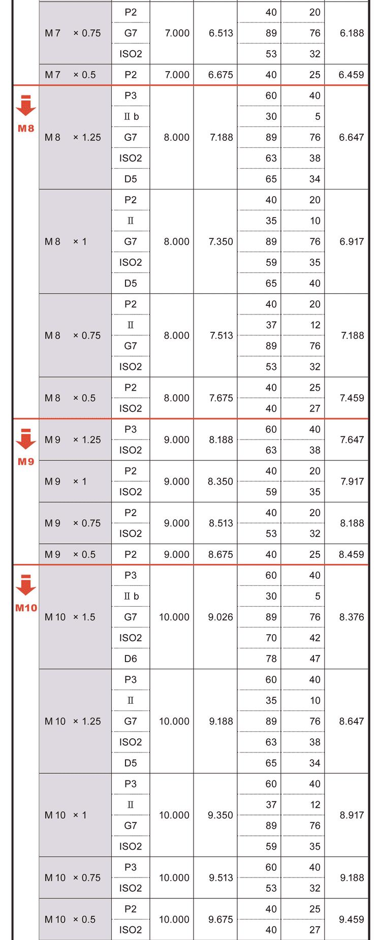
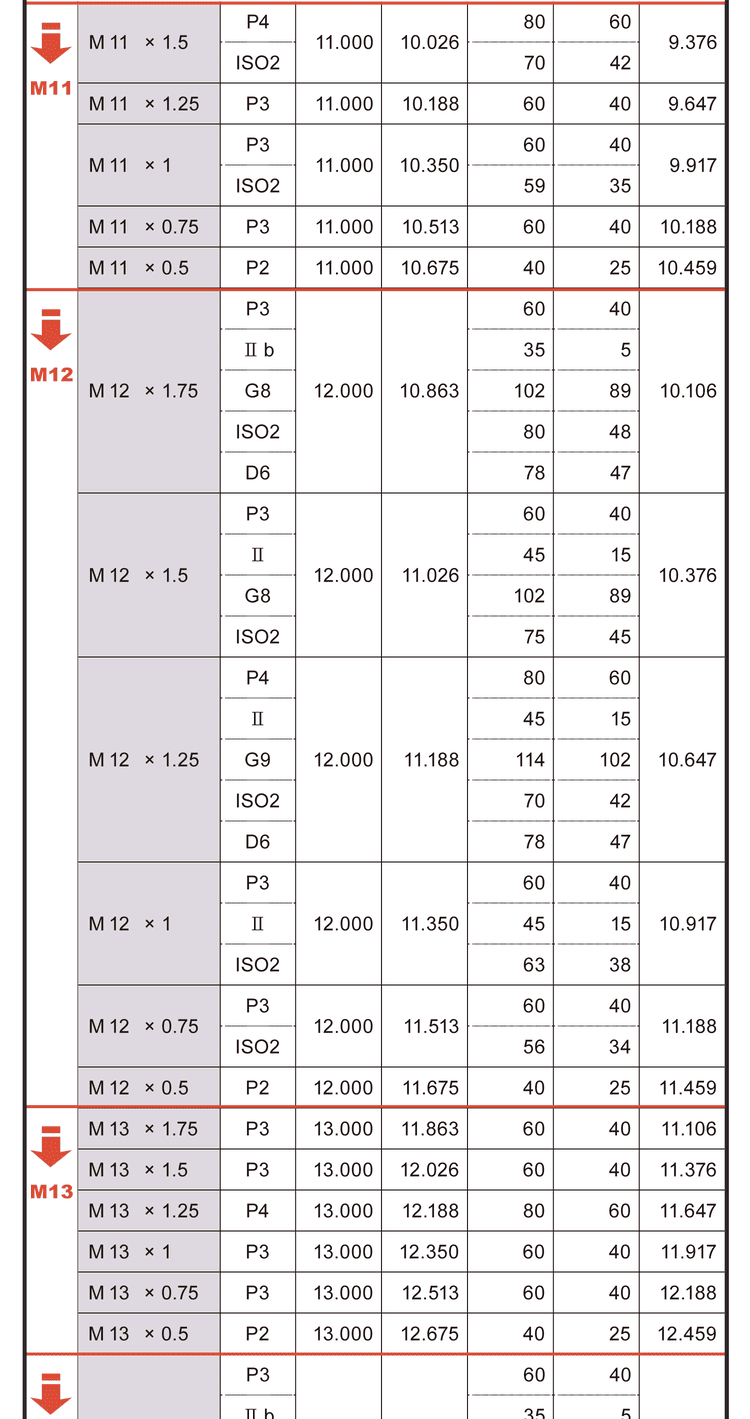
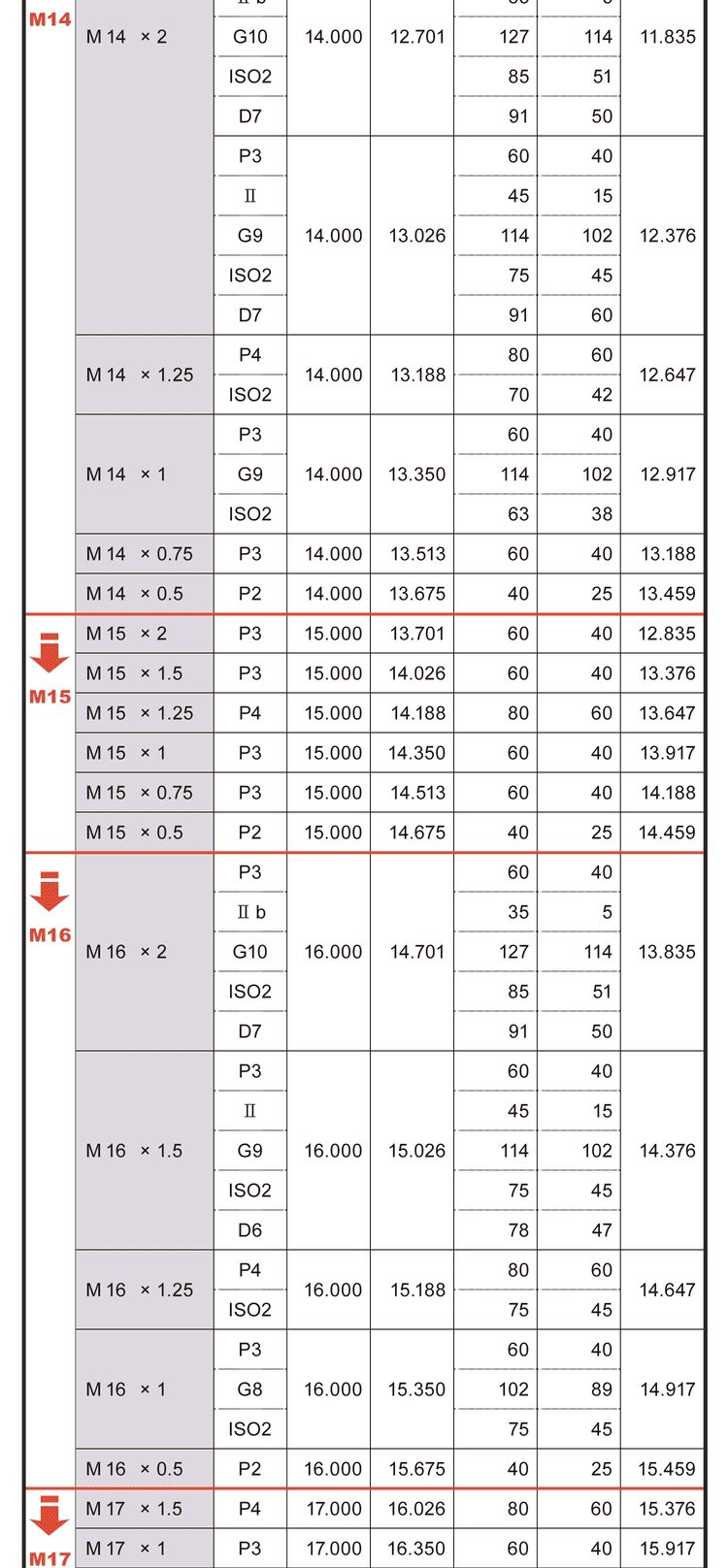
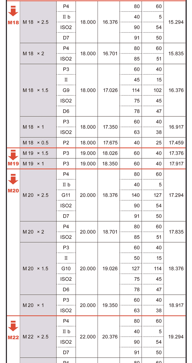
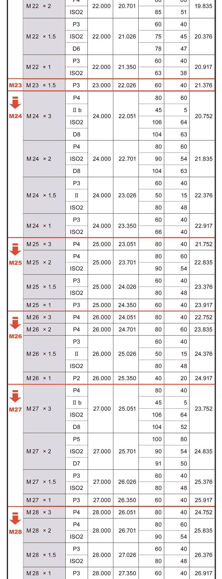
※ Full M1–M48 tolerance charts above; values per the original tables.
4. How to Use the Chart
| Step | Action |
|---|---|
| ① Pick thread size | Choose M size, e.g. M6, M8, M10 |
| ② Confirm pitch | e.g. M6×1, M8×1.25 (fine pitch differs) |
| ③ Read pitch & minor dia | Used to work out the tap-drill (pilot) size |
| ④ Match tolerance grade | Choose P1 or P2 by required precision |
5. Applications
CNC machining sets pilot-hole size accurately and lowers tool wear; mold making secures thread fit and avoids looseness or interference; QC quickly checks whether sizes pass, raising inspection efficiency.
6. Common Mistakes and Fixes
| Mistake | Fix |
|---|---|
| Wrong drill size — threads too tight or loose | Set the pilot hole from pitch & minor dia; check the tap-drill chart |
| Ignoring tolerance grade causes assembly issues | Pick P1 or P2 by application |
| Not accounting for material | Material affects tapping deformation — fine-tune with cutting conditions |
For pilot-hole selection see the Metric Tap Drill Size Chart Guide; for internal-thread tolerance and fit grades see the Tap Thread Tolerance Guide; for unified and imperial standards see the Unified Thread Tolerance Chart and Imperial Thread Tolerance Chart.
General dimensional tolerances outside threads follow a separate system: see the Hole Tolerance Chart for holes, the Shaft Tolerance Chart for shafts, and the Tolerance and Fit Guide for how fits are selected.
FAQ
Q: What's the difference between pitch and minor diameter?
Pitch diameter sets fit tightness and is the most precision-critical size; minor diameter is the root, affects strength and is close to the tap-drill size. Pilot holes are estimated mainly from minor dia and pitch.
Q: How do I set the tap-drill size?
For metric coarse threads, "tap drill ≈ major − pitch" is a common estimate (e.g. M6×1 → about 5.0mm), then fine-tune for material and tap type. See the tap-drill chart for exact values.
Q: P1 or P2 grade?
P1 sits lowest, giving the smallest tapped thread and the tightest fit, for precision parts that need a close fit; P2 sits one step higher with a looser fit, for general machining and assembly. A higher P number moves the tolerance zone up and loosens the fit; every grade has the same width, so a higher number does not mean a wider tolerance.
Q: Why does one M size have different pitches?
Metric threads come in coarse and fine; the same major diameter can have different pitches (e.g. M8×1.25 coarse, M8×1 fine). Different pitch changes pitch, minor and tap-drill sizes, so always confirm the pitch first.
Last updated: 2026-10-09
For the full reading guide on this topic, see Thread Machining: A Complete Reading Guide.