Bolt Hole Size Chart: Socket Cap Clearance & Counterbore Guide
Bolt hole size is a key parameter in mechanical design and assembly, especially for socket-head cap screws that need clearance hole, counterbore and head space considered together. Standardised diameters and depths ensure assembly accuracy and structural strength. This guide gives an M3–M30 bolt hole chart, size symbols and counterbore design rules to help engineers design and machine quickly.
1. What Bolt Hole Size Is
A bolt hole comes in several structures: clearance hole, counterbore and tapped hole. For socket-head cap screws you must consider the bolt major diameter, head diameter and head height to decide whether the head sinks in or stands proud.
2. Size Symbols
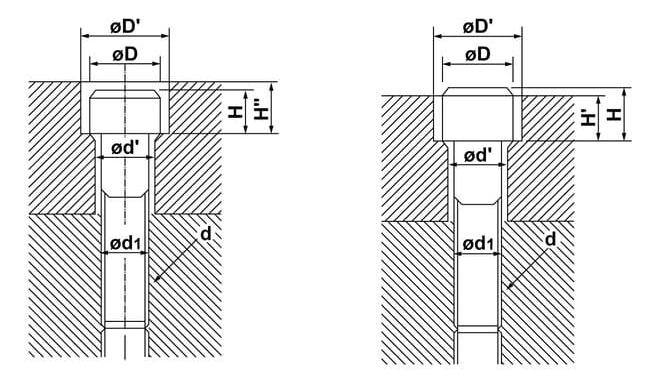
| Symbol | Meaning |
|---|---|
| d | Thread major dia (bolt size) |
| d1 | Nominal diameter of the tapped hole in the base part (same as d) |
| d' | Bolt clearance hole diameter (the drill size) |
| D | Counterbore diameter |
| D' | Wider counterbore diameter (looser design) |
| H | Standard counterbore depth (head flush with the surface; equals the thread nominal diameter) |
| H', H'' | H' shallower (head slightly proud); H'' deeper (head slightly sunk) |
3. Socket Cap Screw Hole Size Chart (M3–M30, reference)
Units: mm. ød' clearance, øD counterbore, øD' looser counterbore, H standard depth, H' shallower, H'' deeper (positions in the cross-sections at the top and the symbol table in section 2).
| Bolt | ød' | øD | øD' | H | H' | H'' |
|---|---|---|---|---|---|---|
| M3 | 3.4 | 5.5 | 6.5 | 3 | 2.7 | 3.3 |
| M4 | 4.5 | 7 | 8 | 4 | 3.6 | 4.4 |
| M5 | 5.5 | 8.5 | 9.5 | 5 | 4.6 | 5.4 |
| M6 | 6.6 | 10 | 11 | 6 | 5.5 | 6.5 |
| M8 | 9 | 13 | 14 | 8 | 7.4 | 8.6 |
| M10 | 11 | 16 | 17.5 | 10 | 9.2 | 10.8 |
| M12 | 14 | 18 | 20 | 12 | 11 | 13 |
| M14 | 16 | 21 | 23 | 14 | 12.8 | 15.2 |
| M16 | 18 | 24 | 26 | 16 | 14.5 | 17.5 |
| M18 | 20 | 27 | 29 | 18 | 16.5 | 19.5 |
| M20 | 22 | 30 | 32 | 20 | 18.5 | 21.5 |
| M22 | 24 | 33 | 35 | 22 | 20.5 | 23.5 |
| M24 | 26 | 36 | 39 | 24 | 22.5 | 25.5 |
| M27 | 30 | 40 | 43 | 27 | 25 | 29 |
| M30 | 33 | 45 | 48 | 30 | 28 | 32 |
The clearance ød' is the drill diameter (e.g. ø9 for M8); for a looser counterbore use the larger øD' (14 mm for M8). The standard depth H equals the thread nominal diameter (8 mm for M8); for a slightly sunk head use the deeper H'', for a slightly proud head the shallower H' (8.6 mm and 7.4 mm for M8).
4. Counterbore Design Rules
A counterbore must satisfy three points: (1) full head containment — counterbore dia D ≥ head dia, depth H ≥ head height; (2) assembly need — a head flush with the surface uses the standard depth H, slightly sunk uses the deeper H'', slightly proud uses the shallower H'; (3) machining — drill first, then mill the counterbore, ideally with a step drill or counterbore cutter. For how a counterbore is reground and why it must never be ground hollow, see Three Tools After the Drill.
5. Reading the Drawing and CNC Tips
The image shows two typical designs: left, the head fully sunk for flush assembly; right, the head partly proud for quick disassembly. CNC tips: precision assembly uses standard counterbore sizes with controlled depth tolerance; general parts can relax the counterbore tolerance for efficiency; high-load uses need more contact area and a flat counterbore floor. For tapped-hole pre-drill sizes see the Tap Drill Size Chart; for hole tolerance and fit see the Tolerance and Fit Guide.
FAQ
Q: Clearance hole vs counterbore?
A clearance hole lets the bolt shank pass through; a counterbore is a larger-diameter recess above the clearance hole that houses the bolt head so it can sit flush or below the surface.
Q: What hole size for an M6 socket cap screw?
M6 clearance is 6.6 mm (the drill size) and the counterbore is 10 mm in diameter, or 11 mm for a looser fit; the standard counterbore depth is 6 mm, leaving the head flush with the surface; the shallower H' is 5.5 mm and the deeper H'' 6.5 mm. Check the specification of the screw you are using.
Q: How is counterbore depth set?
By assembly need: for a head flush with the surface use the standard depth H (equal to the thread nominal diameter, e.g. 8 mm for M8); for a slightly sunk head use the deeper H'', and for a slightly proud head the shallower H'. Either way, keep the counterbore floor flat so the head bears evenly.
Q: How is a counterbore machined?
Drill the clearance hole first, then mill the counterbore with a counterbore cutter (or step drill). Keep the floor flat so the head bears evenly; for precision, control the depth tolerance so the head is neither proud nor over-sunk.
Last updated: 2026-10-17