
Boring Bar Guide: ISO Codes, Material & Selection
Boring bar codes combine shank material, diameter, length, insert shape, clearance angle and clamping system into a standardized system, letting users quickly select the right tool for internal machining. Reading the codes correctly improves bore accuracy and stability, and helps avoid vibration and tool damage in CNC internal turning.
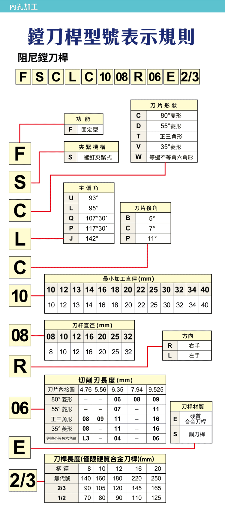
1. Boring Bar Code Structure
A typical code (e.g. FSCLCR…) is built from fields covering tool function, clamping system, insert shape, lead angle, clearance angle, shank size and length, and machining direction. Reading each field lets you quickly identify the spec and speed up selection.
| Field | Meaning |
|---|---|
| Function code | Standard / special type |
| Clamping | Screw, lever, etc. |
| Insert shape | Insert geometry code |
| Lead angle | Tool entering angle |
| Clearance angle | Insert clearance |
| Shank size & length | Diameter and bar length |
| Direction | Left / right hand |
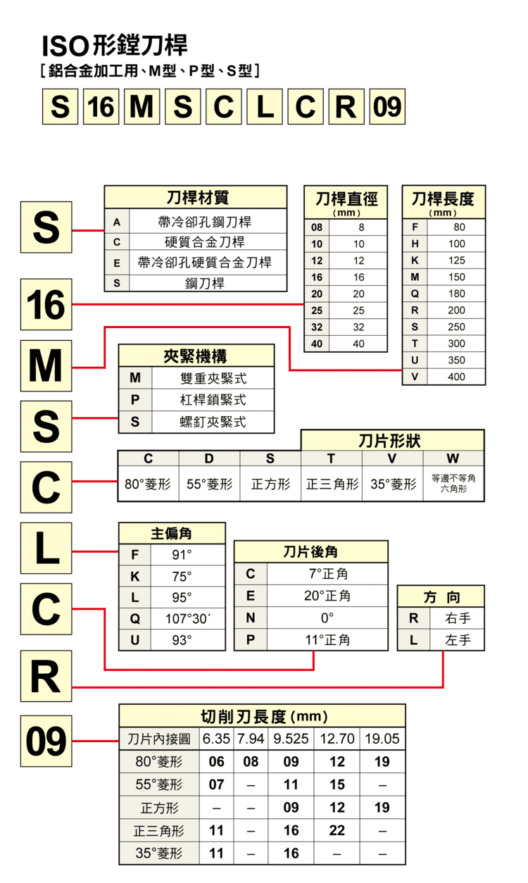
2. Shank Material
Shank material drives rigidity and vibration resistance. Common types are steel, carbide and anti-vibration bars. Deep-hole or long-overhang work favors an anti-vibration bar to suppress chatter; general work uses a steel bar; high accuracy uses a carbide bar.
| Material | Suggested use |
|---|---|
| Steel shank | General machining |
| Carbide shank | High-accuracy machining |
| Anti-vibration bar | Deep-hole machining |
3. Bar Diameter and Capability
Bar diameter affects rigidity and vibration resistance — the larger the diameter, the higher the rigidity — but it must fit within the bore (the bar has to enter the hole). Common diameters are Ø8, Ø10, Ø12, Ø16, Ø20, Ø25 and Ø32 (mm).
| Item | Content |
|---|---|
| Common diameters (mm) | Ø8 / Ø10 / Ø12 / Ø16 / Ø20 / Ø25 / Ø32 |
| Affects | Rigidity, vibration resistance |
| Principle | Larger → stiffer, but must be smaller than the bore |
4. Bar Length and Overhang Ratio
The longer the overhang, the more prone the bar is to vibration. Control the overhang ratio (L/D) and avoid over-long bars to improve stability and surface quality. Overhang ratio is one of the keys to stable internal machining.
5. Insert Shape and Application
Insert shape affects the cutting angle and available space. Small bores are space-limited and favor small-angle inserts (V); general internal work commonly uses C.
| Code | Shape | Suggested use |
|---|---|---|
| C | 80° rhombic | General internal work |
| D | 55° rhombic | Contour / tighter space |
| T | Triangular | General |
| V | 35° rhombic | Small bore, clearance |
6. Lead Angle and Direction
Lead angle affects cutting-force direction and chip flow; common values are 93°, 95°, 107.5° and 117.5°. Direction is coded R (right-hand) or L (left-hand) and must match the workpiece machining direction.
| Item | Content |
|---|---|
| Common lead angles | 93° / 95° / 107.5° / 117.5° |
| Affects | Force direction, chip flow |
| Direction | R: right-hand; L: left-hand |
7. Insert Clearance Angle
The clearance angle gives a gap between the insert and the bore wall. Common values are 0°, 5°, 7° and 11°. A small clearance gives higher rigidity; a large clearance gives lower cutting resistance. Choose by bore size and operation.
| Clearance | Trait |
|---|---|
| 0° / 5° | Small clearance → high rigidity |
| 7° / 11° | Large clearance → low resistance |
8. Clamping, Minimum Bore & Selection
Common clamping methods are screw, lever and double clamp, affecting insert seating and vibration resistance. Always check the "minimum bore diameter" — the bar diameter must be smaller than the bore so it can enter. Overall logic: deep holes use an anti-vibration bar for stability; high accuracy uses a carbide bar with a small-nose insert; general work uses a steel bar with standard inserts. The keys to optimizing internal machining are shank rigidity, overhang control and insert choice — get them right to raise accuracy, cut vibration and extend tool life. For actual cutting conditions, see the Turning Machining Formulas.
FAQ
Q: When should I use an anti-vibration bar?
Use one for deep holes or a large overhang ratio (L/D) where chatter is likely — it suppresses vibration and improves stability and finish. Shallow bores can use a steel bar.
Q: Why does overhang ratio (L/D) matter?
The longer the overhang, the more the bar vibrates, which hurts bore roundness and finish. Keep the ratio down and avoid over-long bars; switch to a carbide or anti-vibration bar when more rigidity is needed.
Q: How do I confirm the bar fits the bore?
Check the bar's "minimum bore diameter" spec — the bar diameter must be smaller than the bore being machined so it can enter. A larger diameter is stiffer but is limited by the bore.
Q: Larger or smaller clearance angle?
A small clearance (0°, 5°) is stiffer and suits stable cuts; a large clearance (7°, 11°) lowers cutting resistance. Choose by bore space and operation to balance rigidity and smooth cutting.
For the full reading guides on this topic, see Insert Selection: A Complete Reading Guide, Vibration and Chatter: A Complete Reading Guide and Hole Accuracy: A Complete Reading Guide.









