Shaft Tolerance Chart: g6, h6 & f7 Values (ISO 286)
The shaft tolerance chart is a key standard in the ISO fit system. Grades such as g, h and f define the allowed deviation of a shaft's size to ensure fit accuracy with the hole. Each band decides whether parts form a clearance, transition or interference fit. This guide covers shaft tolerance grades, code structure, size ranges and fit logic, with a full tolerance reference chart, to help engineers select the right fit in CNC machining and design.
1. What Shaft Tolerance Is
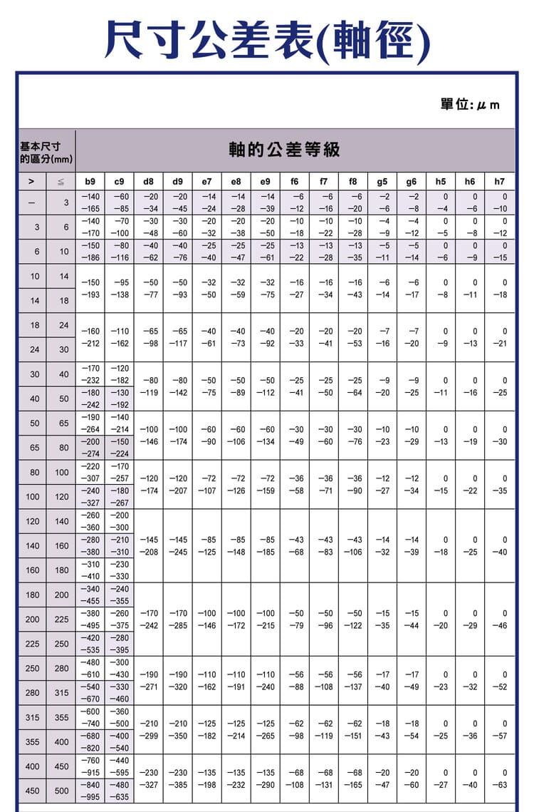
Shaft tolerance is the allowed variation of a shaft's actual size, controlling fit accuracy with the hole. In the chart, the top value is the upper limit and the bottom value the lower limit.
Shaft designations such as h7, g6 or f7 pair with hole tolerances under ISO 286; for hole values such as H7 or H8 see the Hole Tolerance Chart.
2. Code Structure
A shaft tolerance code is a letter (position) plus a number (precision):
| Letter (position) | Meaning |
|---|---|
| h | Datum shaft (upper limit 0, most common) |
| g | Slightly below datum, clearance fit |
| f | Smaller, larger clearance |
| e, d, c, b | Progressively smaller; special / shrink fits |
The number is the IT grade: smaller number, higher precision, narrower band.
3. h Series (Datum Shaft) Example
The h series is the most common standard: upper limit 0, size only decreases. Values grow with size (reference below; use the chart image for exact figures):
| Grade | Deviation | Positioning |
|---|---|---|
| h5 | 0 / very small negative | Precision shafts |
| h6 | 0 / small negative | General precision fits |
| h7 | 0 / larger negative | General use |
4. g, f Series (Clearance Fit)
g series: shaft slightly smaller than the hole, for sliding fits. f series: smaller than g, larger clearance. In the chart g6 and f7 are negative deviations. The d, c, b series deviate more — the shaft is clearly below nominal, used for special or shrink fits.
5. Fit Relationships (Hole vs Shaft)
| Fit type | Common combos | Effect |
|---|---|---|
| Clearance | H7/h6, H8/g6 | Easy assembly, slides |
| Transition | H7/k6, H7/js6, H7/n6 | Precise location |
| Interference | H7/p6, H7/s6, H7/u6 | Press-fit fixing |
Shaft tolerance must be used with the hole tolerance to determine the final clearance or interference.
6. Size Range Effect
From the chart: Ø3 mm tiny, Ø100 mm larger, Ø500 mm much larger — the bigger the size, the wider the allowed machining error.
7. CNC Application Guide
| Need | Suggested shaft tolerance | Application |
|---|---|---|
| High-precision shaft | h5 / h6 | Precision bearings |
| General use | h7 / g6 | Power transmission |
| Loose fit | f7 / e8 | Sliding parts |
For matching hole tolerances see the Hole Tolerance Chart; for fit concepts see the Tolerance and Fit Guide.
Shaft is within spec but it wobbles when it turns? That is orientation/runout tolerance at work — see the Geometric Tolerance Symbols Chart.
FAQ
Q: What is the h6 shaft tolerance?
h6 is a datum shaft: upper limit fixed at 0, negative deviation only, growing with size. Use the chart image or standard table for exact figures and match the correct size range.
Q: Why is the h series upper limit always 0?
h is the datum shaft, defined so the upper limit equals nominal (deviation 0); the shaft is only ever smaller. This mirrors the datum hole H (lower limit 0), making standard fits easy to build.
Q: How do g6 and h6 differ?
h6 has upper limit 0 (datum shaft); g6 is shifted slightly negative, so the shaft is smaller and keeps a steady gap with the hole — good for sliding fits. Same IT6 grade, different band position.
Q: Can shaft tolerance alone define the fit?
No. The fit is set by hole and shaft tolerances together, e.g. H7/h6 or H7/p6. After reading the shaft tolerance, pair it with the hole tolerance (see the hole chart) to know whether it is clearance, transition or interference.
Published: 2026-03-25 | Last updated: 2026-07-23