
Dial & Test Indicator Guide: Setup, Errors & JIS B7503
Dial indicators and test (lever) indicators are the most-used comparison gauges in precision measurement; their accuracy and reliability depend heavily on correct mounting, measuring attitude and error control. This guide covers mounting rules, error types (indication error, hysteresis, repeatability) and measuring force, plus the JIS B7503 standard and floating-zero concept to raise stability and accuracy.
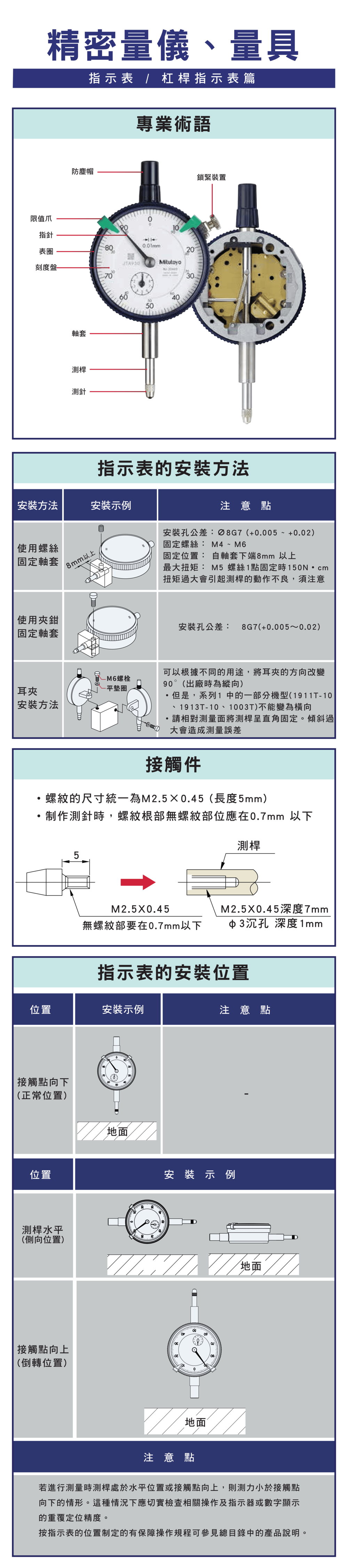
1. Dial vs Test Indicator
Both are comparison tools for flatness, concentricity and runout, CNC setup and mold/precision inspection. A dial indicator has a straight plunger travel; a test indicator uses a swinging lever contact, suiting tight or side-facing spots.
2. Structure and Key Parts
| Part | Note |
|---|---|
| Plunger and stylus | Contact part, transfers displacement |
| Dial and pointer | Show the reading |
| Stem and clamp | Mount to a stand |
| Limit lug and dust cap | Protect the mechanism, keep out dust |
These directly affect sensitivity and accuracy stability.
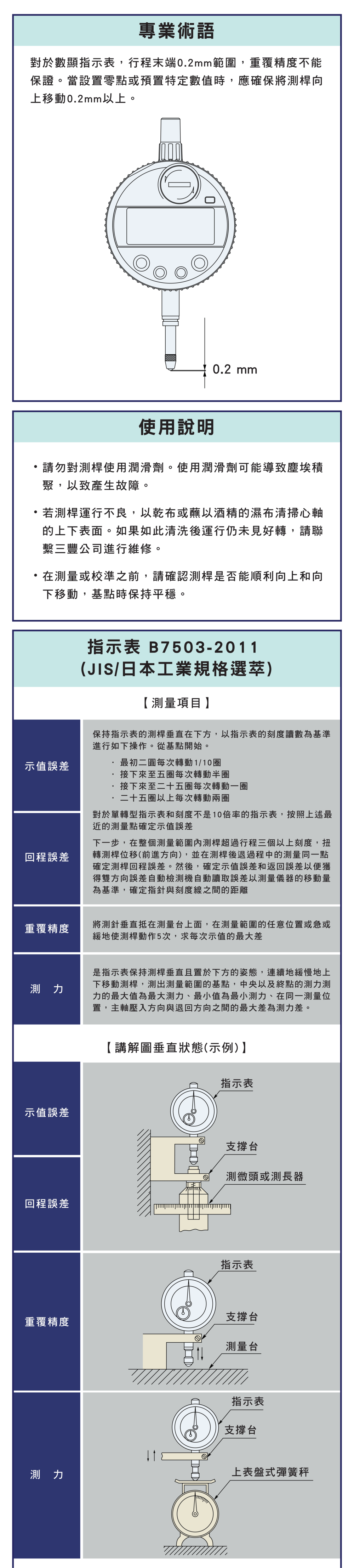
3. Mounting and Cautions
| Item | Rule (reference) |
|---|---|
| Mounting hole tolerance | Ø8 H7 (reference, about 0 to +0.015) |
| Clamp screw | M4–M6 |
| Clamp position | ≥ 8 mm below the stem top |
Keys: over-tight clamping impedes plunger motion; keep the plunger perpendicular to the surface — too much tilt causes error; a test indicator's contact lug can be adjusted as needed.
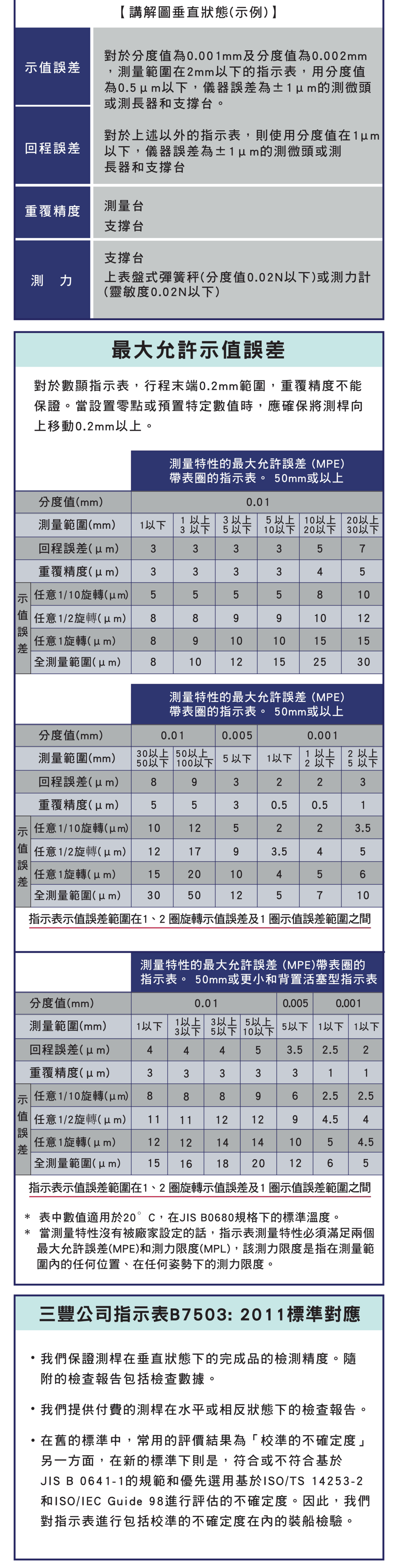
4. Measuring Attitude vs Accuracy
| Attitude | Note |
|---|---|
| Contact down | Best accuracy (standard) |
| Plunger horizontal (side) | Lower force; re-check repeatability |
| Contact up (inverted) | Lowest force, less stable |
5. Main Error Types
| Error | Note |
|---|---|
| Indication error | Reading vs true value; affects accuracy |
| Hysteresis | Forward vs return difference; from backlash and friction |
| Repeatability | Consistency over repeats; reflects stability |
| Measuring force | Too much or too little stylus force causes error |
6. Digital Indicator Notes
The last ~0.2 mm of travel is less stable; leave safe travel when setting zero and avoid measuring at the limit. Digital units zero anywhere but still need proper travel planning.
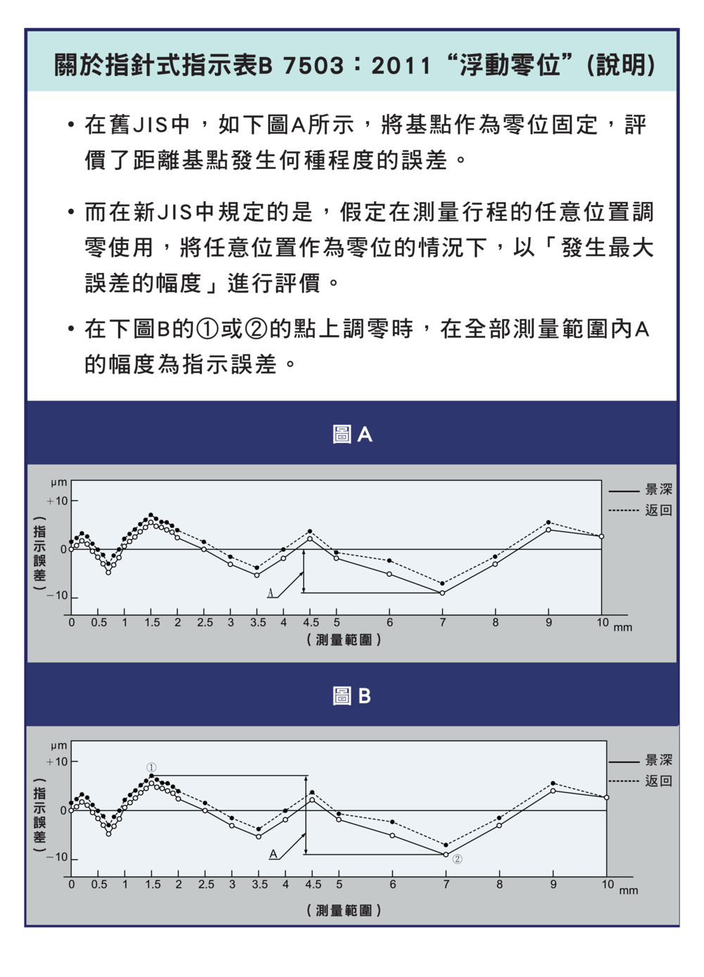
7. JIS B7503 and Floating Zero
JIS B7503 specifies graduation value and accuracy class. The newer standard adds a floating zero — zero can be set anywhere and error is assessed as an overall maximum band, closer to real machining measurement than looking only at a local zone.
8. Use and Maintenance
Do not oil the plunger (attracts dust); clean or service a sticking plunger; before measuring, confirm smooth plunger motion and correct zero. For a calibration reference see the Gauge Block Guide; for roundness/runout see the Roundness & Cylindricity Guide.
FAQ
Q: Dial or test indicator?
A dial indicator has straight, longer travel — good for flatness and depth comparison; a test indicator is small with a swing contact — good for tight spaces, bores and side setup (spindle/part runout). They're often used together.
Q: Why keep the plunger perpendicular?
When tilted, the plunger must travel farther along the tilted path (d / cos θ) to re-contact the surface, so the reading is biased high; the true value equals the reading times cosine (cos θ, which is less than 1), and the error grows with tilt. Test indicators have a similar cosine error, so keep the contact angle small and correct as specified.
Q: How to avoid hysteresis?
Hysteresis comes from backlash and friction. Approach from one direction (unidirectional reading), avoid back-and-forth reads, and clean/service regularly; too little measuring force also enlarges hysteresis.
Q: What if I clamp the stem too tight?
Over-clamping (too much torque) distorts the inner sleeve and makes the plunger stick, worsening hysteresis and repeatability. Clamp ≥ 8 mm below the stem top at a proper torque and confirm the plunger still moves freely.
This article is part of Precision Measurement Complete Guide: Ask What You Are Measuring First, Then Pick the Instrument; that guide shows how the whole topic fits together.









