
CNC Thread Cutting Depth Guide: Pass Strategy & Depth Distribution
In thread cutting, the depth and pass count strongly affect quality, tool life and stability. Constant-volume (V1=V2) or constant-depth (X1=X2) strategies each affect load and chatter differently. Distributing depth sensibly and keeping a small last cut (about 0.025–0.05 mm) lowers vibration and improves surface accuracy; pairing the right infeed method (e.g. modified flank) and conditions further extends tool life and efficiency.
1. Core Concepts of Thread Cutting Depth
In CNC threading, cut depth (ap) sets each pass's load, pass count (n) affects stability and efficiency, and the depth distribution drives tool life and surface quality. The goal is balance between efficiency and stability.
2. Two Main Strategies
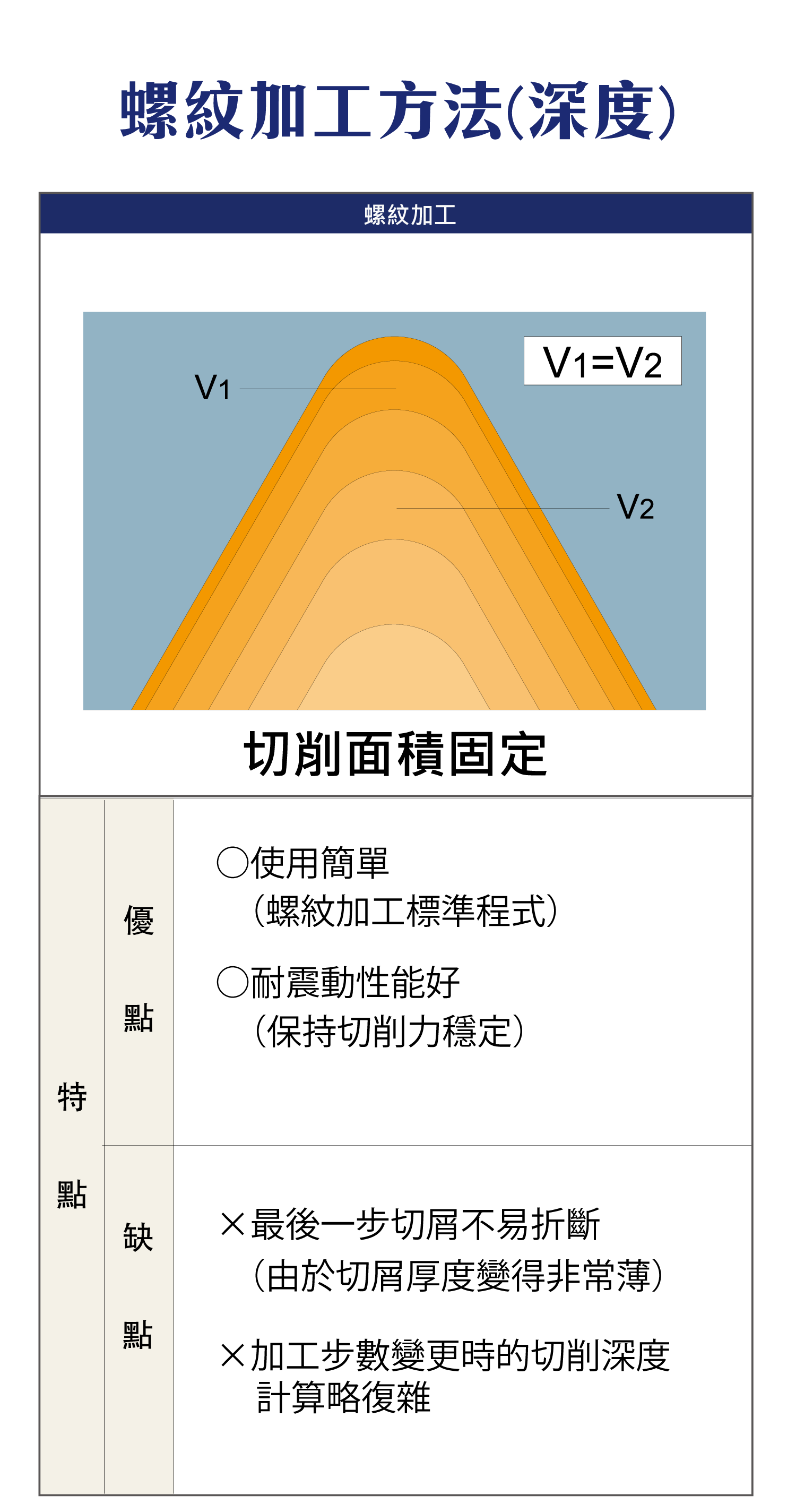
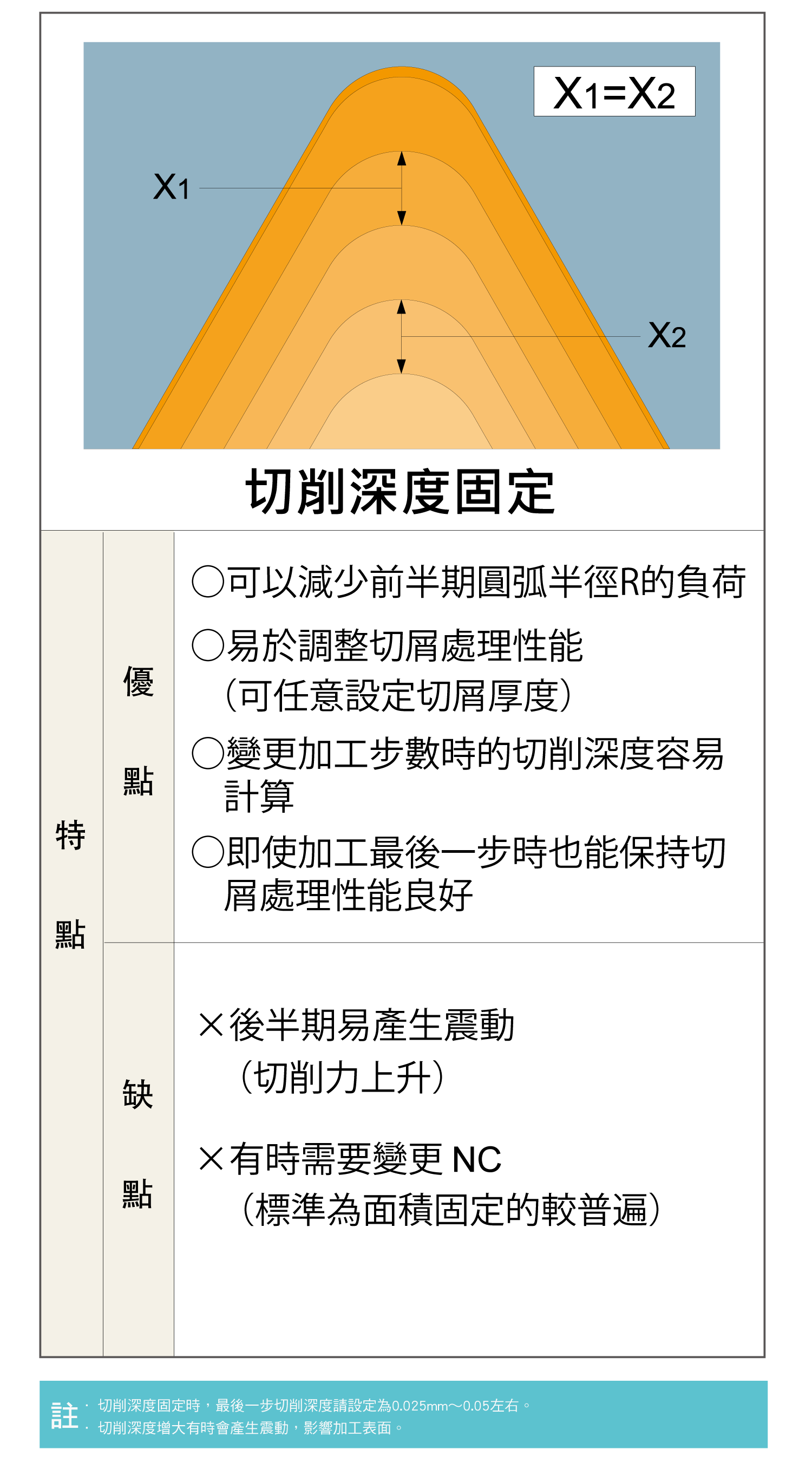
There are two ways to distribute depth: the same cutting area every pass (constant area, also called constant volume, V1 = V2) or the same depth every pass (constant depth, X1 = X2). Built-in threading cycles on lathes usually use constant area as the standard.
| Strategy | Trait | Pros | Cons |
|---|---|---|---|
| Constant area (V1 = V2) | Same area per pass; depth decreases pass by pass | Simple to use; stable cutting force, resists vibration | Last chip is very thin and hard to break; depths must be recalculated if the pass count changes |
| Constant depth (X1 = X2) | Same depth per pass | Less nose-radius load in early passes; chip thickness can be set, chip control stays good to the last pass; easy to recalculate | Cutting force rises in later passes and vibration is likely; some machines need the NC program changed |
3. Cut Depth Calculation
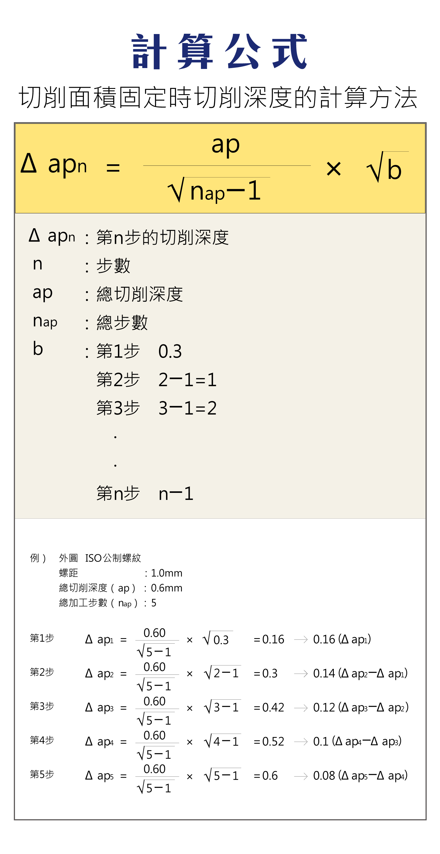
At constant area, the formula below gives the cumulative depth at pass n; the depth actually taken in a pass is this step minus the previous one.
Δapn = ap ÷ √(nap − 1) × √b
| Parameter | Meaning |
|---|---|
| Δapn | Cumulative depth at pass n |
| ap | Total depth |
| nap | Total passes |
| b | 0.3 for pass 1; n − 1 for pass n (n ≥ 2) |
Example: ISO metric external thread, pitch 1.0 mm, total depth 0.6 mm, 5 passes.
| Pass | b | Cumulative depth (mm) | Depth this pass (mm) |
|---|---|---|---|
| 1 | 0.3 | 0.16 | 0.16 |
| 2 | 1 | 0.30 | 0.14 |
| 3 | 2 | 0.42 | 0.12 |
| 4 | 3 | 0.52 | 0.10 |
| 5 | 4 | 0.60 | 0.08 |
4. Key Recommendations
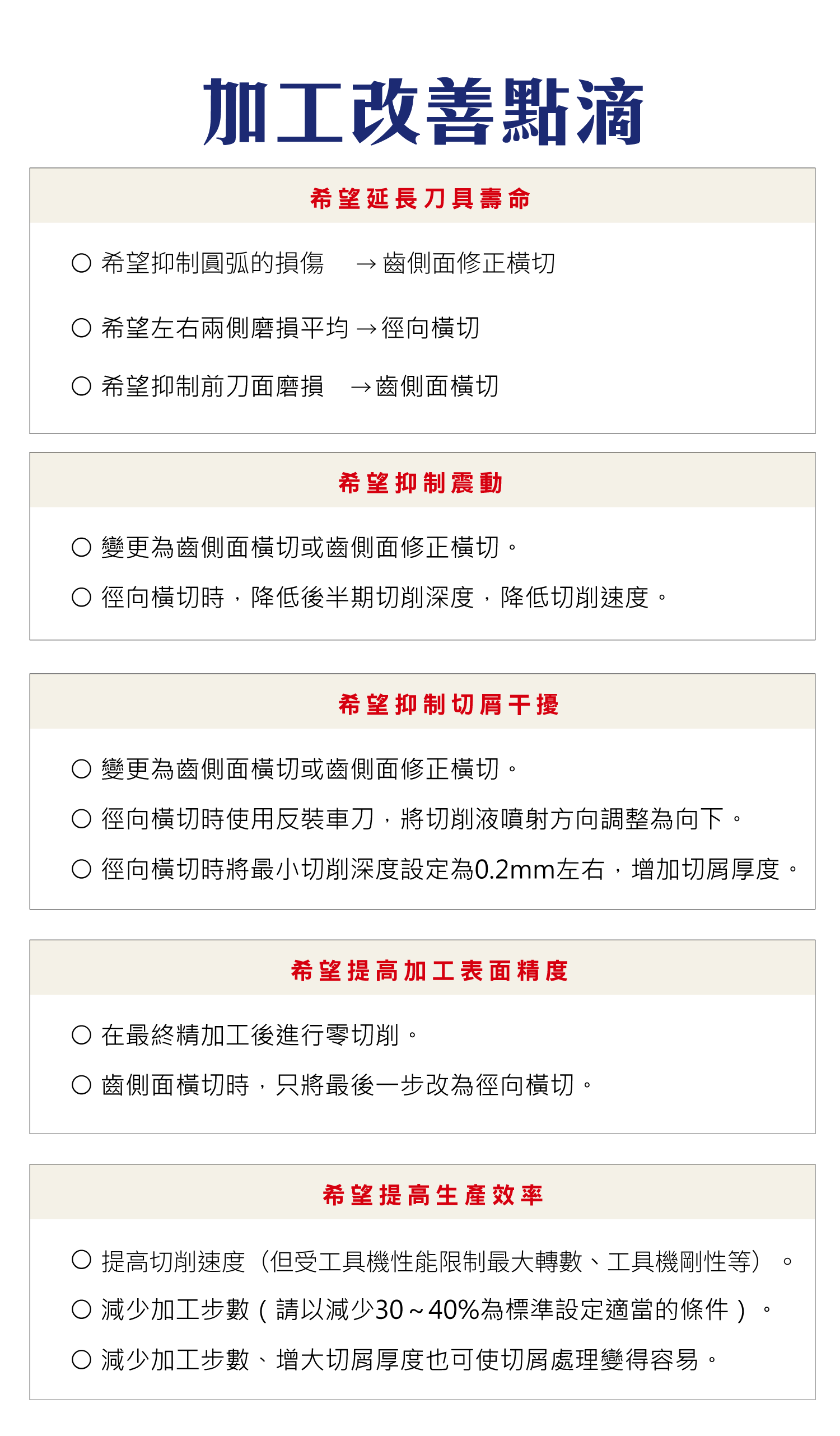
With constant depth, set the last pass to about 0.025–0.05 mm; a deeper last pass can cause vibration and mark the surface. Too large a depth causes chatter, worse surface roughness and shorter tool life.
| Item | Advice / effect |
|---|---|
| Last pass (constant depth) | About 0.025–0.05 mm |
| Depth too large | Chatter, worse finish, shorter tool life |

5. Infeed Methods
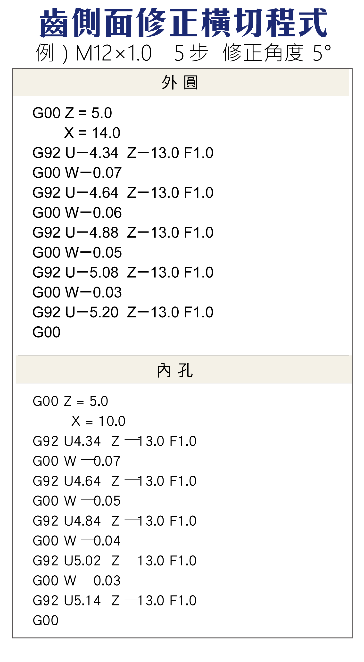
Common infeed methods are radial infeed, flank cutting and modified flank infeed. The modified flank infeed is recommended: it lowers cutting force, reduces vibration, improves surface quality and extends tool life.
| Method | Note |
|---|---|
| Radial infeed | Radial feed; both flanks loaded at once |
| Flank cutting | Feed along the flank; single-side load |
| Modified flank infeed ★recommended | Lower force, less vibration, better surface, longer tool life |
6. Cutting Condition Strategy
Adjust the strategy by goal:
| Goal | Suggested strategy |
|---|---|
| Extend tool life | Use constant-volume cutting |
| Suppress vibration | Reduce cut depth |
| Improve evacuation | Increase later-pass depth |
| Improve surface | Reduce the last cut |
| Improve efficiency | Reduce pass count |
7. Improvement Priorities
Overall, threading can be improved in five ways: distribute load evenly to extend tool life, reduce per-pass depth to suppress vibration, adjust the strategy to improve chips, use a small finish cut to raise surface accuracy, and optimize the pass count for efficiency. Calculate actual speed and feed from your material and machine — see the Turning Machining Formulas; for external/internal thread parameters, see the External Thread Machining Guide and Internal Thread Machining Guide.
For the full reading guide on this topic, see Turning Toolpaths: The Complete Guide.
FAQ
Q: Constant-volume or constant-depth cutting?
Constant area (constant volume, V1=V2) is simple, keeps cutting force stable and resists vibration, and is the standard in threading cycles; its weak point is a very thin last chip that is hard to break. Constant depth (X1=X2) loads the nose less in early passes and makes chips easy to control, but force rises and vibration is likely in later passes. Start with constant area; consider constant depth if chip control is a problem.
Q: How deep should the last pass be?
With constant depth, about 0.025–0.05 mm. Too large causes chatter, worse roughness and shorter tool life; too small increases rubbing and flank wear, so smaller is not always better.
Q: Why is modified flank infeed better?
Radial infeed loads both flanks at once, concentrating force and heat; modified flank infeed cuts mainly along one side with a small correction, lowering force, reducing vibration, improving surface and extending tool life — a common recommendation for thread turning.
Q: How do I reduce threading vibration?
Vibration usually comes from too deep a single pass or uneven load. Reduce per-pass depth, use constant area to keep the force stable, switch to modified flank infeed, and raise machine and clamping rigidity; with radial infeed, lowering the later-pass depth and the cutting speed also helps.
Last updated: 2026-10-21
For the full reading guides on this topic, see Thread Machining: A Complete Reading Guide, Tool Life and Wear: A Complete Reading Guide and Vibration and Chatter: A Complete Reading Guide.









