
End Mill Cutting Conditions Guide | Speed, Feed Rate and Calculation Explained
End mill cutting conditions directly affect machining efficiency, tool life and surface quality. Key parameters include cutting speed (vc), spindle speed (n) and feed rate (vf), calculated together with tool diameter, material properties and depth of cut. Different materials—steel, stainless steel, aluminum and titanium alloy—call for different cutting-speed ranges and feed factors. Correct settings reduce tool wear, improve stability and optimize overall CNC performance.
Why Cutting Conditions Matter
Cutting-condition settings are the core of CNC machining, directly affecting efficiency, surface quality, tool life and machine load. Settings that are too high cause chipping, breakage and poor surfaces; too low reduces efficiency and raises cost.
Basic Calculation Flow
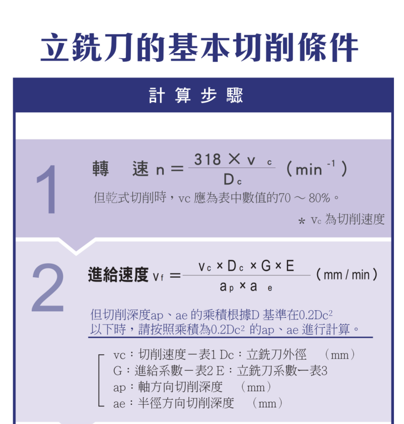
Step 1: Spindle speed n
n = 318 × vc ÷ Dc (min⁻¹)
| Item | Description |
|---|---|
| vc | cutting speed (m/min) |
| Dc | tool diameter (mm) |
| For dry cutting, take vc at 70–80% of the table value. | |
Step 2: Feed rate vf
vf = (vc × Dc × G × E) ÷ (ap × ae) (mm/min)
| Item | Description |
|---|---|
| G | feed factor (Table ②, by diameter and material) |
| E | tool factor (Table ③, by tool type and flute count) |
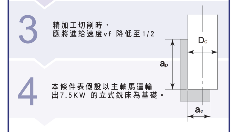
| ap | axial depth of cut (mm) ae: radial depth of cut (mm) |
| When ap × ae is at or below 0.2Dc², calculate using ap, ae whose product equals 0.2Dc². | |
Step 3: Finishing correction—reduce feed rate vf to 1/2 for finishing.
※ This condition table assumes a vertical milling machine with a 7.5 kW spindle motor.
Cutting Speed Selection (vc)
Cutting speed varies by workpiece material and tool grade (HSS series, carbide series), in m/min.
Table ① Cutting speed vc (HSS series)
| Workpiece | Hardness (HB) | Untreated | G series | SG・AG series |
|---|---|---|---|---|
| General structural steel | ~180 | 25~30 | 35~45 | 40~50 |
| Carbon steel | ~230 | 20~30 | 30~40 | 35~45 |
| Alloy / quenched & tempered steel | ~280 (40HRC) | 15~20 | 20~30 | 25~35 |
| Mold / pre-hardened steel | ~320 | 10~15 | 15~25 | 20~30 |
| Heat-resistant / titanium alloy | ~380 | 8~12 | 15~20 | 15~25 |
| High-hardness steel | 40HRC~ | ~5 | ~10 | ~15 |
| Stainless steel | ~180 | 10~15 | 15~25 | 20~25 |
| Cast iron | ~200 | 25~35 | 35~45 | 40~50 |
| Aluminum / aluminum alloy | — | 50~70 | 70~90 | 80~90 |
| Copper alloy / brass | — | 40~60 | 60~80 | 70~80 |
Table ① Cutting speed vc (carbide series)
| Workpiece | Hardness (HB) | X's mill | X's mill GEO/GS mill | DLC mill |
|---|---|---|---|---|
| General structural steel | ~180 | 70~90 | 80~120 | — |
| Carbon steel | ~230 | 60~80 | 80~100 | — |
| Alloy / quenched & tempered steel | ~280 (40HRC) | 50~70 | 70~90 | — |
| Mold / pre-hardened steel | ~320 | 40~50 | 50~60 | — |
| Heat-resistant / titanium alloy | ~380 | 30~40 | 40~50 | — |
| High-hardness steel | 40HRC~ | ~25 | ~30 | — |
| Stainless steel | ~180 | 40~50 | 50~60 | — |
| Cast iron | ~200 | 60~80 | 70~100 | — |
| Aluminum / aluminum alloy | — | 80~120 | 100~150 | 100~200 |
| Copper alloy / brass | — | 80~100 | 100~120 | 80~150 |
Feed Factor (G)
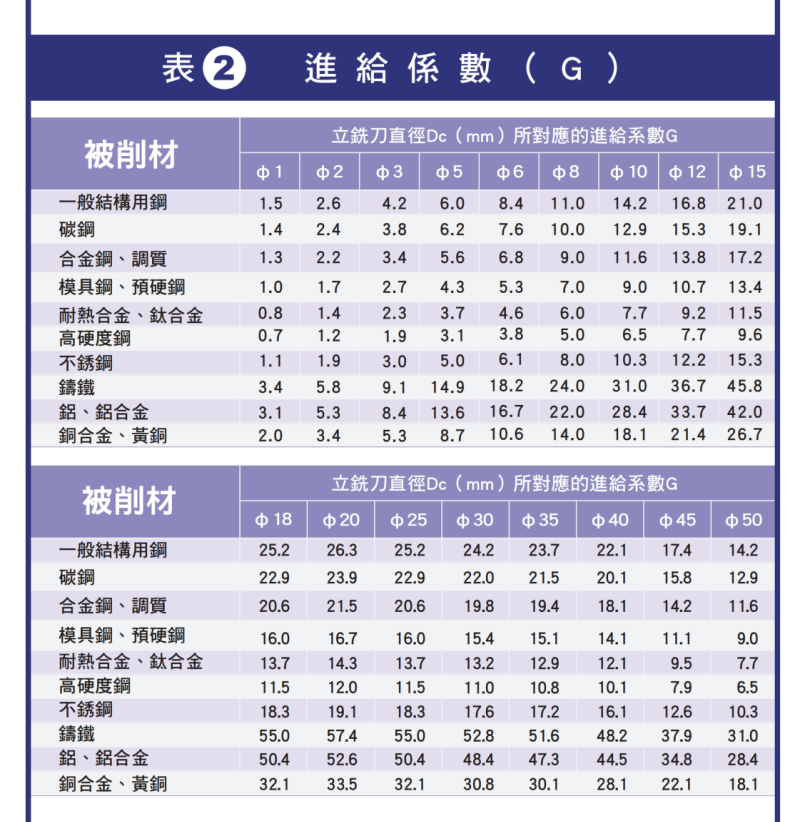
The feed factor G varies by tool diameter (φ1–φ50) and workpiece material, used in the vf formula.
Table ② Feed factor G (φ1–φ15)
| Workpiece | φ1 | φ2 | φ3 | φ5 | φ6 | φ8 | φ10 | φ12 | φ15 |
|---|---|---|---|---|---|---|---|---|---|
| General structural steel | 1.5 | 2.6 | 4.2 | 6.0 | 8.4 | 11.0 | 14.2 | 16.8 | 21.0 |
| Carbon steel | 1.4 | 2.4 | 3.8 | 6.2 | 7.6 | 10.0 | 12.9 | 15.3 | 19.1 |
| Alloy / quenched & tempered | 1.3 | 2.2 | 3.4 | 5.6 | 6.8 | 9.0 | 11.6 | 13.8 | 17.2 |
| Mold / pre-hardened steel | 1.0 | 1.7 | 2.7 | 4.3 | 5.3 | 7.0 | 9.0 | 10.7 | 13.4 |
| Heat-resistant / titanium | 0.8 | 1.4 | 2.3 | 3.7 | 4.6 | 6.0 | 7.7 | 9.2 | 11.5 |
| High-hardness steel | 0.7 | 1.2 | 1.9 | 3.1 | 3.8 | 5.0 | 6.5 | 7.7 | 9.6 |
| Stainless steel | 1.1 | 1.9 | 3.0 | 5.0 | 6.1 | 8.0 | 10.3 | 12.2 | 15.3 |
| Cast iron | 3.4 | 5.8 | 9.1 | 14.9 | 18.2 | 24.0 | 31.0 | 36.7 | 45.8 |
| Aluminum / aluminum alloy | 3.1 | 5.3 | 8.4 | 13.6 | 16.7 | 22.0 | 28.4 | 33.7 | 42.0 |
| Copper alloy / brass | 2.0 | 3.4 | 5.3 | 8.7 | 10.6 | 14.0 | 18.1 | 21.4 | 26.7 |
Table ② Feed factor G (φ18–φ50)
| Workpiece | φ18 | φ20 | φ25 | φ30 | φ35 | φ40 | φ45 | φ50 |
|---|---|---|---|---|---|---|---|---|
| General structural steel | 25.2 | 26.3 | 25.2 | 24.2 | 23.7 | 22.1 | 17.4 | 14.2 |
| Carbon steel | 22.9 | 23.9 | 22.9 | 22.0 | 21.5 | 20.1 | 15.8 | 12.9 |
| Alloy / quenched & tempered | 20.6 | 21.5 | 20.6 | 19.8 | 19.4 | 18.1 | 14.2 | 11.6 |
| Mold / pre-hardened steel | 16.0 | 16.7 | 16.0 | 15.4 | 15.1 | 14.1 | 11.1 | 9.0 |
| Heat-resistant / titanium | 13.7 | 14.3 | 13.7 | 13.2 | 12.9 | 12.1 | 9.5 | 7.7 |
| High-hardness steel | 11.5 | 12.0 | 11.5 | 11.0 | 10.8 | 10.1 | 7.9 | 6.5 |
| Stainless steel | 18.3 | 19.1 | 18.3 | 17.6 | 17.2 | 16.1 | 12.6 | 10.3 |
| Cast iron | 55.0 | 57.4 | 55.0 | 52.8 | 51.6 | 48.2 | 37.9 | 31.0 |
| Aluminum / aluminum alloy | 50.4 | 52.6 | 50.4 | 48.4 | 47.3 | 44.5 | 34.8 | 28.4 |
| Copper alloy / brass | 32.1 | 33.5 | 32.1 | 30.8 | 30.1 | 28.1 | 22.1 | 18.1 |
Tool Factor (E)
The tool factor E depends on end mill type (standard, heavy-cutting, roughing, carbide) and flute count, used in the vf formula.
| Type | Length | Representative products | 2-flute | 3-flute | 4-flute | 5-flute | 6-flute | 8-flute |
|---|---|---|---|---|---|---|---|---|
| HSS standard end mill | Short | NATAC, G-standard, SG-FAX, AG (2–3 flute) | 1.5 | 1.8 | — | — | — | — |
| Standard | Carbide type, G-standard/mid-long, SG-FAX, AG | 0.5 | 1.2 | 1.5 | — | 2.0 | — | |
| Long | Carbide long, G-long, SG-FAX long, AG long | 0.5 | — | 0.8 | — | 1.0 | — | |
| Heavy-cutting end mill | Standard | Heavy-cutting, AG/SG-FAX heavy-cutting | — | — | 1.8 | — | 2.4 | — |
| Long | Heavy-cutting long, AG/SG-FAX heavy-cutting long | — | — | 1.1 | — | 1.5 | — | |
| Roughing end mill | Short | SG-FAX roughing short | — | 1.9 | 2.3 | 2.7 | 3.0 | — |
| Short | SG, AG roughing standard short | — | 1.6 | 2.0 | 2.3 | 2.6 | — | |
| Standard | Roughing mid-long, GS roughing, SG coarse-pitch | — | 1.3 | 1.6 | 1.8 | 2.0 | — | |
| Long | Roughing long, AG/SG roughing long | — | 1.0 | 1.2 | 1.4 | 1.5 | — | |
| Carbide series | Standard | X's mill (high-helix/radius/multi-flute/stainless), GS mill | 0.8 | 1.0 | 1.2 | — | 1.6 | 1.8 |
| Standard | X's mill GEO, GEO slotting/radius/Kovar type | 1.0 | 1.2 | 1.5 | — | — | — | |
| Long | X's mill long, GEO long, carbide long | 0.5 | — | 0.7 | — | 0.8 | 1.0 |
Note: the short-length roughing end mill row lists two representative products with different factors; take the value for the product you actually use.
Depth of Cut Settings
Depth of cut is split into axial ap and radial ae. Notes:
| Item |
|---|
| ap × ae must not exceed the tool's load limit. |
| A recommended baseline is about 0.2Dc². |
| The longer the tool overhang, the lower the rigidity and the greater the deflection—reduce depth and load accordingly; see End Mill Length vs Deflection. |
Practical Setting Tips
| Item | Description |
|---|---|
| Roughing | raise feed rate and depth of cut, prioritizing efficiency. |
| Finishing | lower feed rate (vf to 1/2) and control depth, prioritizing accuracy and surface quality. |
| Dry machining | reduce cutting speed to 70–80% to avoid edge overheating. |
Improper cutting conditions accelerate tool wear and chipping; see End Mill Wear Analysis.
No Catalog for Your Cutter? Where to Start the Conditions
Without a catalog, do not guess numbers: borrow a starting point, correct it for the job, then converge with test cuts.
| Step | What to do |
|---|---|
| ① Borrow a start | Use Tables ①–③ in this guide with the same material, tool type and flute count |
| ② High-efficiency or general | Use the high-efficiency set only if machine rigidity, workpiece rigidity and chip evacuation are all good; otherwise use the general set |
| ③ Correct for stability | For unstable setups—long overhang, poor clamping, thin walls—ISCAR multiplies cutting speed by 0.7 |
| ④ Correct for tool life | For longer life, lower the speed: ISCAR’s values assume 20 minutes of life; for 60 minutes multiply speed by 0.8 |
| ⑤ Converge with test cuts | For finishing, start below the starting value and raise it step by step until surface roughness is just good enough |
Do not reverse step ⑤: in finishing, the feed limit is set by surface quality, not tool strength, so backing down from the limit can scrap every part along the way.
Steps ③ and ④ are ISCAR’s factors for its own tools (per the ISCAR Die and Mold Making Guide)—treat them as direction only when borrowing them; step ② follows the selection rule in the Mitsubishi catalog.
FAQ
How do I calculate end mill spindle speed?
n = 318 × vc ÷ Dc, where vc is cutting speed (m/min) and Dc is tool diameter (mm). Look up cutting speed by material first, then apply the formula.
How do I calculate feed rate vf?
vf = (vc × Dc × G × E) ÷ (ap × ae). G is the feed factor (Table ②, by diameter and material) and E the tool factor (Table ③, by tool type and flute count); halve vf for finishing.
Do I adjust conditions for dry machining?
Yes. For dry cutting, take cutting speed vc at 70–80% of the table value to reduce edge heat load and avoid premature wear.
How do I set the depth-of-cut limit?
ap × ae must not exceed the tool's load limit; a baseline of about 0.2Dc² is recommended. When the product is at or below 0.2Dc², derive ap and ae from 0.2Dc². The table assumes a 7.5 kW vertical milling machine.
For the full reading guide on this topic, see Machining Calculation Reading Guide.
This article is part of End Mills: The Complete Guide - Know the Cutter, Choose It, Set the Conditions; Toolpaths Are Another Line; that guide shows how the whole topic fits together.
Published: 2026-03-17 | Last updated: 2026-10-21









