
Mounting and Balancing a Grinding Wheel: Fit, Flanges, Two-Stage Balance and Amplitude Check
A wheel that shakes—or even bursts—on the spindle is usually not a bad wheel but bad mounting and balance. This covers, in order: the pre-mount checks, how much bore-to-shaft clearance to leave, the two flange rules, how mounting differs by shape, and the two balance thresholds plus the two-stage balance and amplitude check for a new wheel.
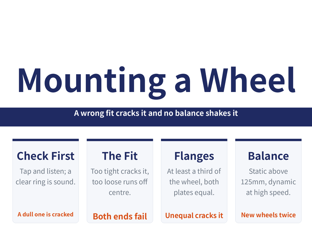
1. Before mounting: four checks you cannot skip
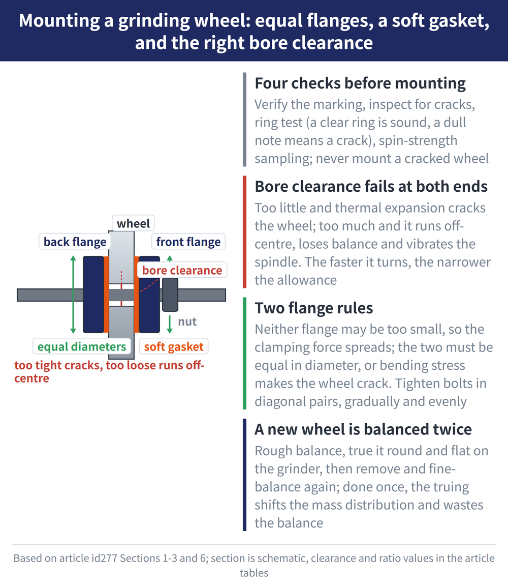
A wheel with cracks or defects must never be mounted. Run four checks first:
| Check | How |
|---|---|
| Marking | Verify abrasive, grit, grade, shape and size; never use an unmarked or unclear wheel; the safe speed must match the spindle rpm—never over-speed |
| Visual | Inspect the surface for cracks or damage by eye or with an aid |
| Ring (tap) test | With the wheel dry and upright, tap the side lightly with a 200–300g mallet; a clear ring means sound, a dull or hoarse sound means a crack—do not use |
| Spin strength | Sample-test spin strength per batch; do not mount an untested batch |
For how to read each field of the marking (abrasive, grit, grade, structure, bond, speed), see Reading a Grinding Wheel Marking.
2. Bore-to-shaft clearance: too tight cracks, too loose runs off-center
Both extremes fail: too little clearance and thermal expansion during grinding cracks the wheel; too much and the wheel runs off-center, loses balance and vibrates the spindle. The clearance must fall within a range.
| Bore d (mm) | Standard wheel (mm) | High-speed wheel (mm) |
|---|---|---|
| d ≤ 100 | 0.1–0.8 | 0.1–0.5 |
| 100 < d ≤ 250 | 0.2–1.0 | 0.2–0.6 |
| d > 250 | 0.2–1.2 | 0.2–0.8 |
The pattern: a high-speed wheel allows a narrower clearance than a standard one—the faster it turns, the less off-center it tolerates.
3. Two flange rules, plus the gasket
The flanges that clamp the wheel have two rules you cannot break:
① Neither the back nor the front flange may be smaller than 1/3 of the wheel OD. This spreads the clamping force over a larger area and avoids concentrated pressure cracking the wheel.
② The two flanges must be equal in diameter. Unequal flanges put a bending stress on the wheel and make it more likely to crack—more easily overlooked than "too small". This is not just shop wisdom: EN 13218 and ANSI B7.1 both require the two flanges to have the same outside diameter and the same bearing surface.
Also place a 0.5–1mm soft gasket (asbestos rubber sheet, resilient cardboard or leather) between flange and wheel face. Tighten multiple bolts in diagonal pairs, in sequence, gradually and evenly; never tighten around the circumference in order or torque one bolt down in one go. Aim for "drives without slipping", not maximum tightness. The paper gasket has rules of its own: fit a new one every second wheel change, and wheels over 400 mm in diameter must always be mounted with one.
4. Different shapes mount differently
Four shapes take four different mounting methods; use the wrong one and even a precise wheel will not run true.
| Wheel type | Mounting |
|---|---|
| Large-bore straight wheel | Clamp between two stepped flanges first, then fit onto the spindle taper and lock with the clamp nut |
| Small-bore straight or cup wheel | Mount directly on the spindle or extension shaft through a plain flange or washer |
| Internal-grinding wheel | Clamp or cement onto an extension shaft first, then fit the shaft to the internal-grinding spindle |
| Cylinder wheel for vertical surface grinders | Cemented to the flange with sulphur |
5. Balance: two thresholds decide how far you go
Uneven density, an asymmetric shape or an off-center mount make the wheel axis miss the spindle axis—out of balance. At speed it vibrates, and in severe cases it damages the grinder or bursts. Two thresholds set how far to go:
| Threshold | Balance needed |
|---|---|
| Diameter > 125mm | Must be balanced so the mass center meets the axis; static balance is enough in general |
| Speed > 50 m/s (high speed) or precision grinding | Dynamic balance is required |
Static balance means mounting the wheel on a balancing arbor, resting it on a level balancing way and rocking it, then moving the balance weights in the flange groove until the wheel stays put in any position. After balancing, and before fitting to the spindle, run the crack check once more.
6. A new wheel is balanced twice, with an amplitude check
A large new wheel (usually over 250mm) is not done after one set of weights—it takes two stages:
Rough balance → true it round and flat on the grinder with a diamond point → remove and fine-balance again. Do it only once and the truing shifts the mass distribution, wasting the balance. The wheel passes when it stays stable in any circumferential position.
How good the balance is gets a quantitative amplitude check (spindle front end, wheel side, excerpted):
| Point / direction | Good balance | Poor balance |
|---|---|---|
| Spindle front, horizontal | ≤0.3 μm | ≥1.2 μm |
| Spindle front, vertical | ≤0.2 μm | ≥0.25 μm |
7. FAQ
Q: The wheel shakes on the spindle—is the wheel bad?
Not necessarily. First check the mounting method, whether the fit clearance is too large, and whether it was balanced. Four shapes take four mounting methods; a wrong method or no balance both cause shake—not always a bad wheel.
Q: Is a tighter bore fit always better?
No. Too tight and thermal expansion during grinding cracks the wheel; too loose and it runs off-center. It must fall in range, e.g. 0.1–0.8mm for a standard wheel under 100mm bore.
Q: Must the two flanges be the same size?
Yes. Back and front flanges must be equal in diameter and neither smaller than 1/3 of the wheel OD. Unequal flanges bend-stress the wheel and raise the crack risk.
Q: When is dynamic balance mandatory?
For high-speed grinding above 50 m/s, or precision grinding, dynamic balance is required; otherwise static balance is enough for wheels over 125mm diameter.
This article is part of Grinding Wheels and Machines: The Complete Guide - Reading the Wheel, Mounting It, Dressing It, and Tracing Defects; that guide shows how the whole topic fits together.
Published: 2026-08-16|Updated: 2026-08-16









