Laser Micrometer: OD Measurement, Error & Alignment
A laser micrometer is a high-accuracy non-contact device that measures outer diameter, spacing and shape change by laser occlusion, widely used for wire, fiber, rollers and precision parts. This guide covers its measuring principle, error sources, mounting/alignment conditions and applications to raise stability and production quality control.

1. What a Laser Micrometer Is
It measures by light occlusion: an emitter and receiver form a measuring zone; when a part passes it blocks the beam, and the system converts the blocked width into size. Traits: non-contact, high speed and accuracy, ideal for in-line inspection.
2. Structure and Interchangeability
The unit usually has an emitter (laser), a receiver and a display/control unit. It needs a matching ID module to configure, and different series may not be interchangeable.
3. Conditions and Accuracy Factors
| Factor | Improvement |
|---|---|
| Part shape (round, irregular) | Calibrate with a standard |
| Surface roughness, reflection | Increase scans and average |
| Laser visibility | Keep the environment stable |
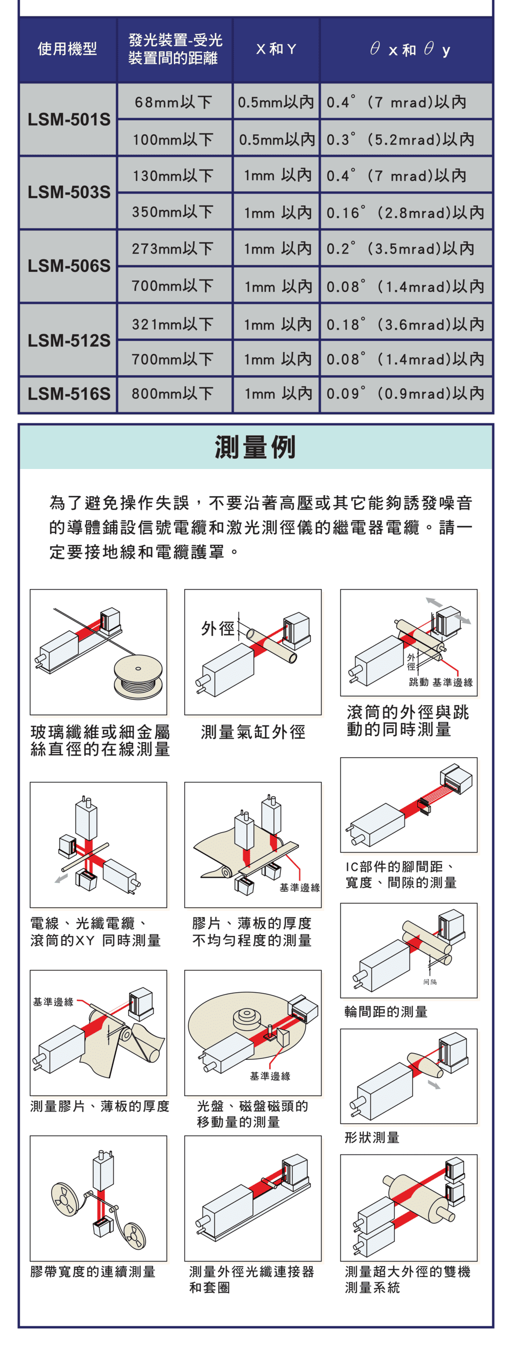
4. Mounting and Optical-Axis Alignment (Key)
To reduce error, control these geometric deviations:
| Deviation | Note |
|---|---|
| Parallel (X) | Emitter and receiver axes must be parallel |
| Angle (θx) | Tilt affects accuracy |
| Height (Y) | Datum faces must align |
| Angle (θy) | Control up/down angular error |
5. Electrical Noise and Signal Stability
Key measures: do not route parallel to high-voltage cables, use grounded shielded cable, and reduce EMI. For communication it supports RS-232C to a computer for real-time data, suiting automated lines.
6. Laser Safety
The unit uses a low-power visible laser at Class 2; avoid direct beam viewing and follow safety labelling.
7. Accuracy and Model Range
| Item | Range (by model) |
|---|---|
| Measuring range | 68 mm–800 mm (the mountable baseline distance between emitter and receiver, not the measurable workpiece OD range; actual measuring range is per each model's factory specification sheet) |
| Installation XY tolerance | Installation/calibration tolerance in the X/Y directions (not measurement accuracy; actual measurement accuracy is per each model's factory specification sheet) |
| Angular error | ~0.08°–0.4° |
8. Typical Applications
Used for wire and fiber diameter, tape/film thickness, roller OD and runout, IC pin pitch and spacing, and optical/precision part sizing — enabling real-time in-line measurement, multi-axis synchronous measurement and large-part stitching. For deeper shape-error analysis see the Roundness & Cylindricity Guide.
FAQ
Q: How does it work?
By light occlusion: the emitter sends a parallel laser, the part blocks part of the beam, and the receiver reads the "blocked width", converting it to diameter. Being non-contact, it suits high-speed in-line measurement of soft or hot parts.
Q: Why align the optical axis?
If emitter and receiver axes are not parallel or have angular/height deviation, the blocked width departs from true, causing size error. Control X parallelism, θx/θy angle and Y height — this is the core of accuracy.
Q: Readings unstable — what to do?
Calibrate with a standard, increase scans and average, stabilise the environment (temperature/vibration/dust), and confirm no parallel high-voltage routing and proper grounded shielding. Reflective or irregular parts also matter — adjust lighting or filter outliers.
Q: Is a Class 2 laser safe?
Class 2 is a low-power visible laser; the blink reflex gives basic protection, but never stare into the beam long or view it through optics, and follow the labelling. Normal in-line measurement use is safe.
This article is part of Precision Measurement Complete Guide: Ask What You Are Measuring First, Then Pick the Instrument; that guide shows how the whole topic fits together.
Published: 2026-03-23 | Last updated: 2026-10-20