Roundness & Cylindricity Guide: Tolerances, LSC/MZC & UPR
Roundness and cylindrical-form measurement is core to precision-machining quality control, assessing roundness, cylindricity, concentricity and runout. This guide covers geometric-tolerance definitions, measuring principles, roundness evaluation methods (LSC, MZC, MCC, MIC), filtering and UPR analysis to raise accuracy and machining stability.
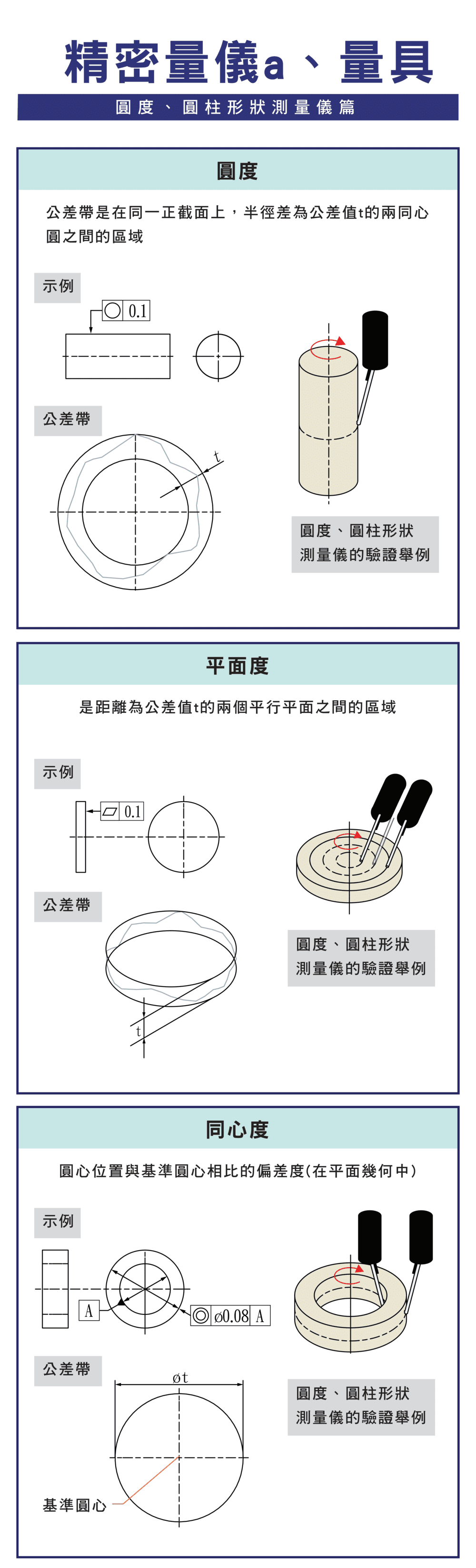
1. Common Geometric Tolerances
| Tolerance | Definition | Use |
|---|---|---|
| Roundness | Radial gap between two concentric circles in one section | Shafts, bearings, seal faces |
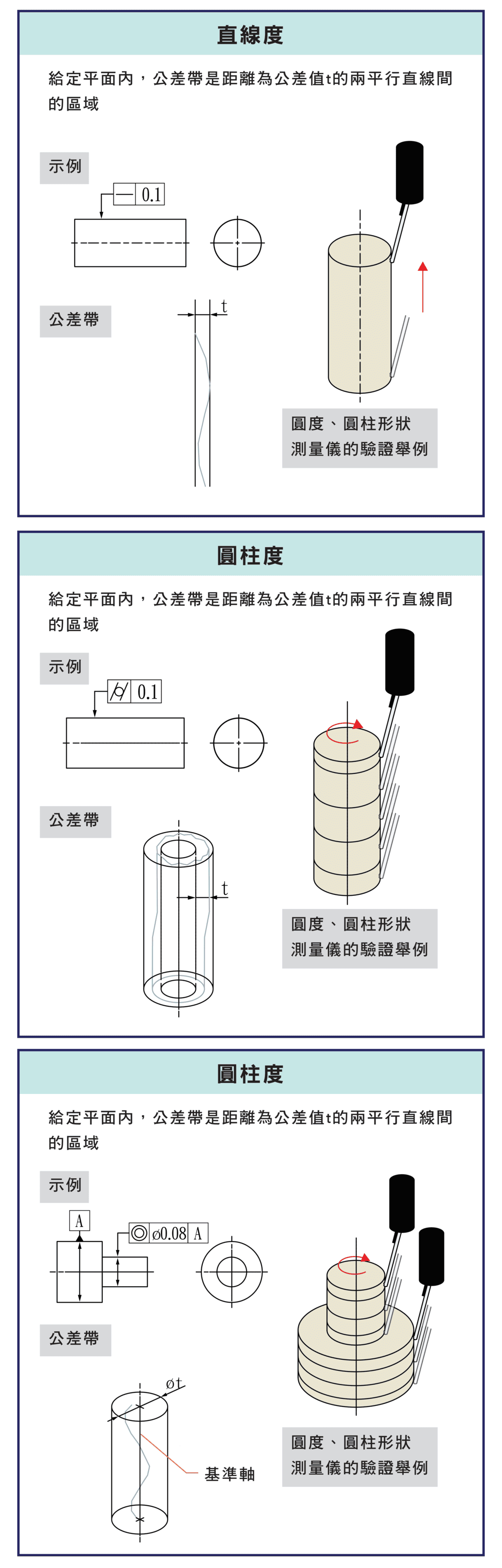
| Cylindricity | 3D cylindrical zone controlling overall form | High-precision shafts, fit accuracy |
| Concentricity | Actual centre vs datum centre deviation | Shaft-bore fit, rotational stability |
| Flatness | Distance between two parallel planes | Datum faces, mold contact faces |
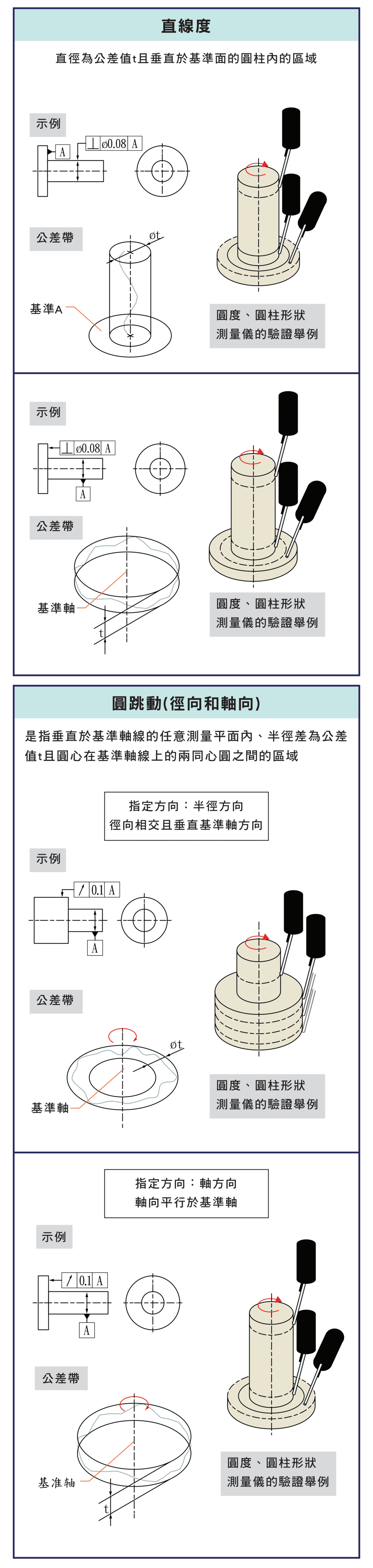
| Straightness | Between two parallel lines in a plane | Axial accuracy, guideway accuracy |
For how these symbols are marked on a drawing and what the tolerance zones look like, see the Geometric Tolerance Zones and Measuring Geometric Tolerance guides. Runout here is a workpiece-drawing geometric tolerance — tool runout (TIR) is a different matter; see Tool Runout (TIR) and Control.
2. Runout
Radial runout is perpendicular to the axis, assessing rotational eccentricity; axial runout is parallel to the axis, assessing face wobble; total runout combines roundness and straightness error, covering overall rotational accuracy.
3. Key Setup Before Measurement
Centering: the part centre must align with the rotation axis to avoid eccentricity error. Leveling: the axis must be parallel to avoid an oval error from tilt. This strongly affects measurement accuracy.

4. Roundness Evaluation Methods (Key)
| Method | Definition |
|---|---|
| Least Squares (LSC) | Minimises squared error, most common |
| Minimum Zone (MZC) | Minimises the two-circle radial gap |
| Min Circumscribed (MCC) | Defined by the circumscribed circle |
| Max Inscribed (MIC) | Defined by the inscribed circle |
Different methods give different results — choose per the standard.

5. Filtering Effect on Roundness
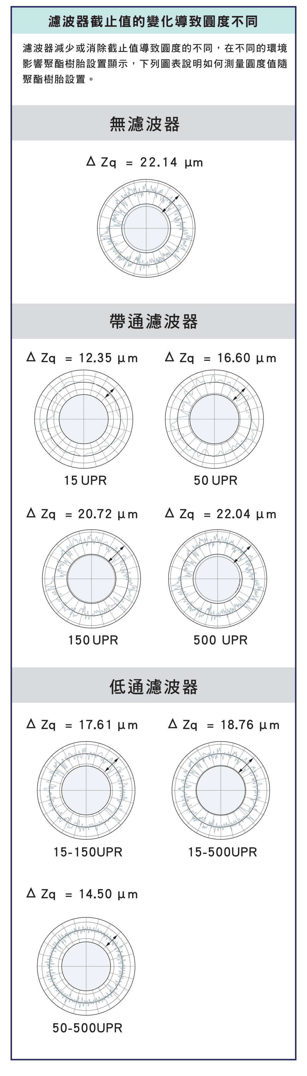
Filter settings change the result: no filter keeps all error, band-pass analyses specific frequencies, low-pass removes high-frequency noise. Undulations per revolution (UPR) separate frequency content: the lower the UPR, the closer it is to form error (mounting, clamping); the higher, the closer to machining texture, tool effects and surface roughness. Typical causes by band are in the table in section 6.
6. UPR Analysis and Machining Problems
| UPR | Likely cause |
|---|---|
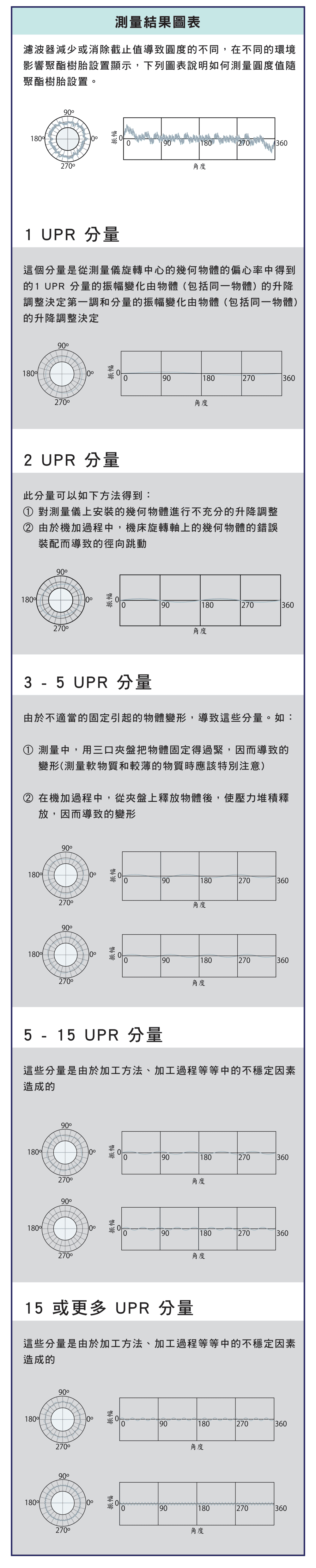
| 1 UPR | Eccentricity, related to centering |
| 2 UPR | Poor mounting, axis offset |
| 3–5 UPR | Clamping distortion, uneven load |
| 5–15 UPR | Unstable machining |
| 15+ UPR | Machining texture, tool and surface roughness |
7. Cylindricity and Overall Form Control
Cylindricity uses a 3D tolerance zone to control overall form error, especially important for high-precision shafts and sealing fits. Combining section roundness with axial straightness fully reflects a part's rotational and fit accuracy. For measurement-uncertainty concepts see the CMM Accuracy & Uncertainty Guide.
FAQ
Q: Roundness vs cylindricity?
Roundness is the circular error of a single section (two concentric circles' radial gap); cylindricity is 3D, covering roundness across many sections plus axial straightness and taper, controlling overall form — stricter than roundness.
Q: How to choose LSC, MZC, MCC, MIC?
LSC (least squares) is most general and noise-robust; MZC (minimum zone) gives the smallest roundness value per ISO; MCC (circumscribed) suits shaft OD fits; MIC (inscribed) suits bores. Choose by the drawing and fit function, and avoid mixing them.
Q: Why center and level first?
If the part centre is off the rotation axis it creates a 1 UPR false eccentricity; tilt turns a circle into an oval. Centering and leveling remove these setup errors so you measure true form, not a fixturing artefact.
Q: Can UPR help find machining problems?
Yes. Low UPR mostly comes from mounting and clamping (1 eccentricity, 2 mounting, 3–5 clamping distortion); mid (5–15) is often unstable machining; 15+ reflects machining texture, tool and surface roughness. The UPR spectrum lets you target the process fix.
This article is part of Precision Measurement Complete Guide: Ask What You Are Measuring First, Then Pick the Instrument; that guide shows how the whole topic fits together.
Published: 2026-03-22 | Last updated: 2026-10-29