ISO Fits Explained: Clearance, Transition & Interference
Before you pick a tolerance number, decide what the joint has to do once assembled: slide, press together, or never move again. This guide walks that order — settle the type of fit first, then choose hole-basis or shaft-basis, and only then land on a grade and the callout that goes on the drawing. It covers when each of the three fit types applies, what going wrong looks like on the finished part, and how to choose between the two basis systems, so you can specify it yourself.
1. Tolerance and Fit Basics
Dimensional tolerance is the range a part’s size is allowed to vary (stated in µm); a fit is the relationship between a hole and a shaft once assembled: clearance, transition or interference. For how to read the upper- and lower-case letters and the numbers, and what the three fit types mean, see Reading Tolerance and Fit; this guide carries on from there: picking the grade, choosing the basis system and settling the fit code.
Dimensional tolerance is not the whole story — geometric tolerance covers shape and position too. See What Is Geometric Tolerance.
2. Tolerance Grades (IT)
| IT grade | Precision | Typical use |
|---|---|---|
| IT5–IT7 | High precision | Precision fits, bearing bores |
| IT8–IT10 | General machining | Structural / common parts |
| IT11–IT12 | Looser machining grades | Non-mating faces |
| IT13–IT16 | Roughing (first operations) | Blanks left for later machining |
| IT17–IT18 | Stock forming | Rolling, drawing, forging and casting |
A smaller grade number means higher precision — but also higher machining cost.
3. Hole-Basis vs Shaft-Basis System
| System | Datum | Note |
|---|---|---|
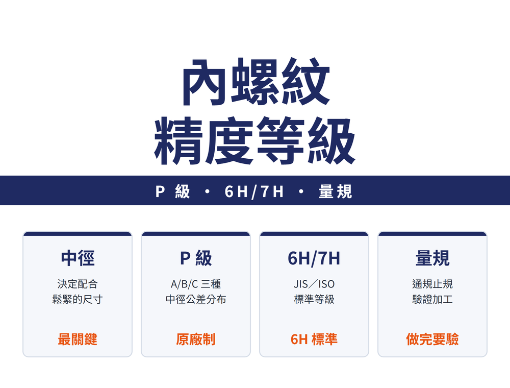
| Hole basis | H7 as datum | Fix hole, vary shaft; most common, easy to manage |
| Shaft basis | h6 as datum | Fix shaft, vary hole; for existing standard shafts |
4. The Three Fit Types
| Fit type | Character | Use | Common combos |
|---|---|---|---|
| Clearance | Hole larger than shaft, always a gap | Sliding, rotating parts | H7/g6, H8/f7 |
| Transition | Slight clearance or interference | Precise location, removable | H7/k6, H7/js6, H7/n6 |
| Interference | Shaft larger than hole, press/heat fit | Permanent, torque transfer | H7/p6, H7/s6, H7/u6 |
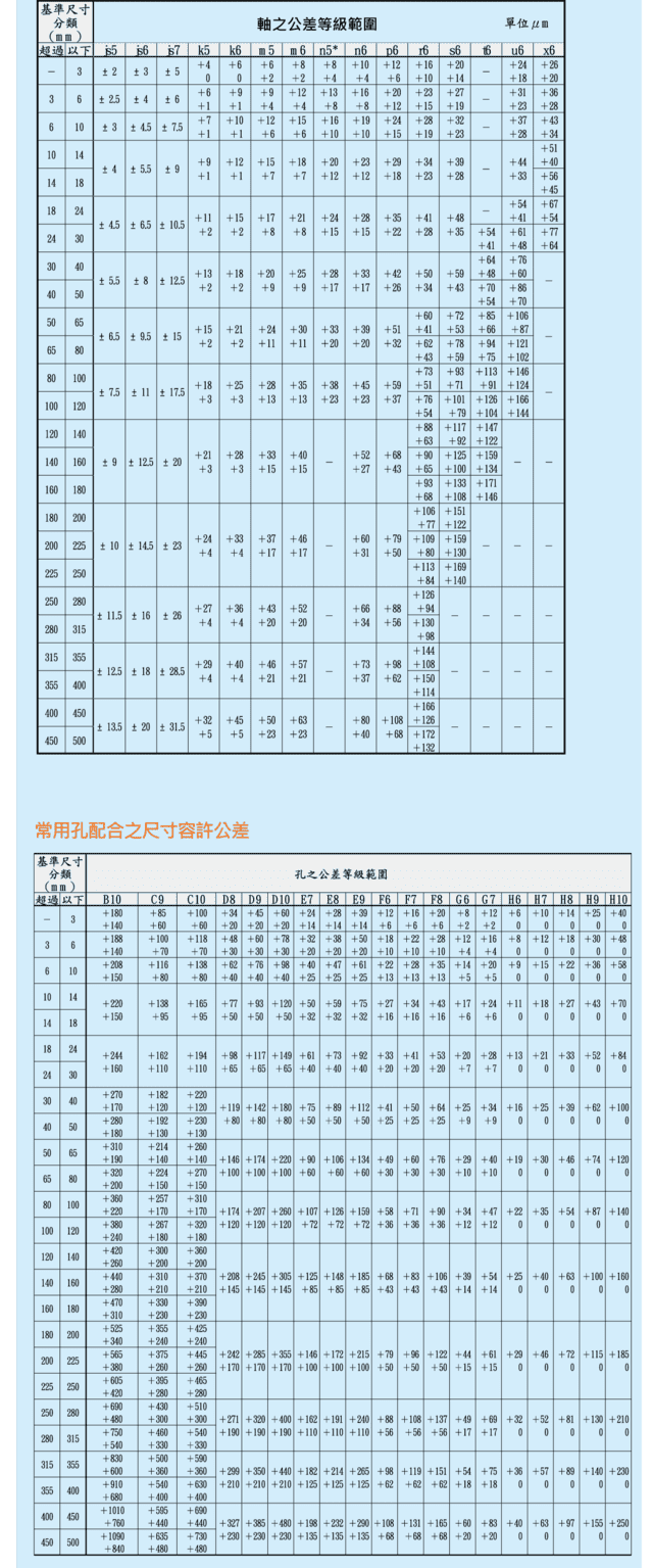
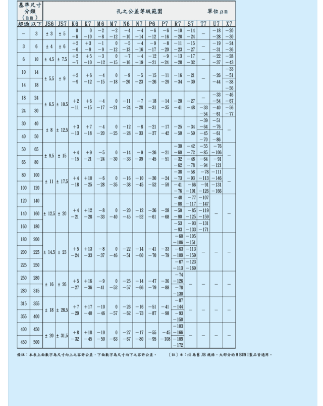
How loose or tight a code really is only shows when you put the hole and shaft limits side by side. Take φ25 (in the over 24 up to 30 mm range): an H7 hole is 25.000–25.021 mm (+21/0 µm).
| Fit | Shaft range (mm) | Max clearance | Max interference | Result |
|---|---|---|---|---|
| H7/g6 | 24.980–24.993 (-7/-20 µm) | 41 µm | — (min clearance 7 µm) | Clearance fit |
| H7/k6 | 25.002–25.015 (+15/+2 µm) | 19 µm | 15 µm | Transition fit |
| H7/p6 | 25.022–25.035 (+35/+22 µm) | — (min interference 1 µm) | 35 µm | Interference fit |
How to work it out: max clearance = hole upper limit − shaft lower limit; max interference = shaft upper limit − hole lower limit. A negative result means that side never occurs — for H7/g6 the “max interference” is negative, so every pairing has clearance.
The same H7/p6 at 3 mm and below (H7 = +10/0, p6 = +12/+6 µm) can open up to 4 µm of clearance and becomes a transition fit. So a fit code cannot be judged apart from its size range: the drawing shows the same code, but a small part may not end up tight.
5. Application Classes and Selection
| Part role | Suggested fit | Goal |
|---|---|---|
| Moving (slide/rotate) | Clearance fit | Smooth motion |
| Locating | Transition fit | Positional accuracy |
| Fixed | Interference fit | Strong joint, torque transfer |
The table above sets the direction; to land on an actual code, use the finer classes in the next two sections (based on the application examples in JIS B 0401; only the shaft paired with the most common H7 hole is listed, with c9 and d9 noted for H8/H9 holes). How to read them: first ask whether the joint has to move and whether it has to come apart, then go from loose to tight and take the first class that fits. From h6 to n6 the parts can still be dismantled without damage; from p6 up they are hard to take apart without damage, so keep anything that must come apart out of that range.
6. Finer Classes of Clearance Fit: c9 to g6
| Class | Shaft for an H7 hole | Assembly and motion | Typical uses |
|---|---|---|---|
| Loose running | c9 (with H9) | Needs a large gap: thermal expansion, large location error, long engagement, or lower cost | Piston rings and ring grooves, loose fit of safety pins |
| Free running | e7 (also d9 with H8/H9) | General rotating and sliding parts with good lubrication; also bearings at high temperature, speed or load | Crankshaft main journals, general moving parts |
| Running | f7 | Enough clearance to move; grease-lubricated bearings at normal temperature | General shafts and bushings |
| Precision running | g6 | Precise motion with no looseness; continuous rotation in light-load precision machines | Keys and keyways, lever pins in linkages |
7. Finer Classes of Transition and Interference Fit: h6 to x6
| Class | Shaft for an H7 hole | Assembly and motion | Typical uses |
|---|---|---|---|
| Sliding (transition) | h6 | Can be pushed by hand when oiled, high location accuracy | Gears in precision gear trains |
| Push fit (transition) | js6 | High-precision location with no relative movement; wooden or lead mallet | Spigot fit between joining flanges |
| Driving fit (transition) | k6, m6 | Steel hammer or hand press; m6 allows no clearance at all | Hydraulic piston on shaft, flange on shaft |
| Light press (transition) | n6 | Needs considerable force; the fit carries a small load | Flexible coupling plate and gear (driven side) |
| Press fit (interference) | p6, r6 | Needs great force; the fit carries a substantial load, r6 suits large parts | Gear on shaft, coupling on shaft |
| Heavy press, shrink and freeze fits (interference) | s6, t6, u6, x6 | Permanent assembly by heavy pressing, heating or cooling | Fixing bushings, drive gear on its rim |
The table files h6 under transition because that is how this selection table groups it. Worked from the limits, an H7 hole has a lower deviation of 0 and an h6 shaft an upper deviation of 0, so the minimum clearance is exactly zero and the pair never interferes — which is why section 4 and the FAQ class H7/h6 as a clearance fit under the ISO three-way split. Both describe the same numbers; they differ only in which side the h6 class is filed under.
8. What a Wrong Fit Looks Like
A wrong fit often passes inspection and only shows up at assembly or after some running time. Check against these four cases:
| What went wrong | What you see | How to avoid it |
|---|---|---|
| Too loose where it should be tight (e.g. a bearing ring under rotating load given clearance) | The mating faces slip against each other (creep): wear, heat and, in bad cases, seizure; once creep starts it is hard to stop, and a locknut will not prevent it | Give the ring under rotating load an interference fit; use clearance only for the ring under stationary load |
| Too tight where it must come apart (e.g. a press-fit grade on a part that is serviced regularly) | It will not go in or will not come out, and forcing it damages the parts | For parts that must come apart without damage, stay within the transition fits (h6–n6); p6 and up are hard to dismantle |
| Too much interference (e.g. bearing inner ring on its shaft) | The inner ring may crack; the bearing loses its internal clearance after mounting, runs hot and wears out early | According to NACHI technical data, interference above 1/1000 of the bearing bore can damage the inner ring; keep it at or below 1/1500 |
| Every size measures in tolerance, yet it will not assemble | The problem is usually not size tolerance but form or position (e.g. roundness, straightness, coaxiality) | Add geometric tolerances to the drawing; see Tolerance and Fit Basics |
9. How Fit Tolerances Are Written on a Drawing
The same tolerance band can be written four ways on a drawing, all meaning the same thing. Using φ25 H7 (hole 25.000–25.021 mm):
| Method | On the drawing | Watch for |
|---|---|---|
| Tolerance symbol | φ25H7 | Symbol height matches the dimension figures |
| Upper/lower deviation | φ25 +0.0210 | Upper deviation on top, lower below, with the figures aligned |
| Limit dimensions | 25.02125.000 | Maximum limit on top, minimum below |
| Symbol plus limit dimensions | φ25H7 (25.02125.000) | Limits in brackets, the minimum limit aligned with the dimension figures |
The four are interchangeable, but a drawing that gives only the code (φ25H7) has to be looked up and turned into limits before machining; see the Hole Tolerance Chart and Shaft Tolerance Chart.
Dimensions with no tolerance shown: no tolerance on the dimension does not mean no tolerance. Under CNS rules the general tolerance is normally stated in or next to the title block; for machined parts the Taiwanese standard is CNS 4018. Check the title block for which standard and which class apply; if it says nothing, ask the customer rather than assuming a class.
10. Tolerance vs Size
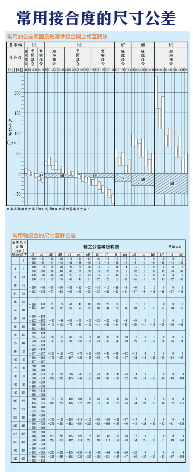
At the same grade, the larger the size, the wider the tolerance band (machining and measurement error grow with size). Selection must balance function, machining capability and assembly method to optimise reliability and cost. For full hole and shaft values, see the Hole Tolerance Chart and Shaft Tolerance Chart.
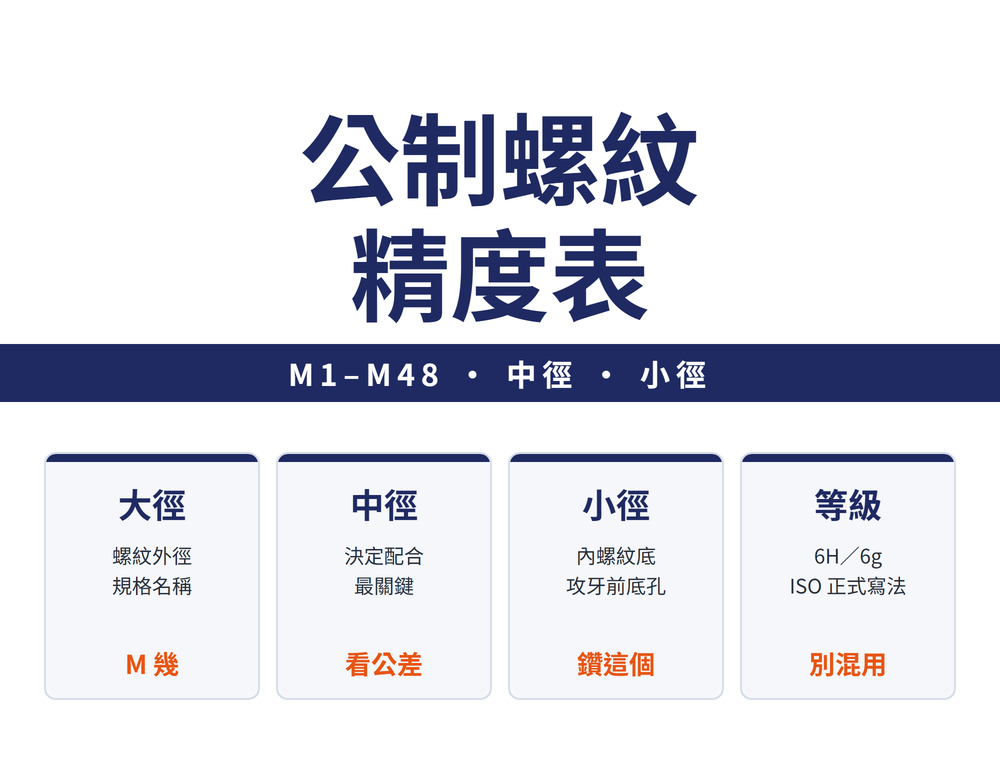
Thread tolerances are a separate system: they control pitch and minor diameters rather than hole or shaft sizes — see the Metric Thread Tolerance Chart.
FAQ
Q: What does H7/h6 mean?
H7/h6 pairs an H7 hole with an h6 shaft; both deviations start from zero, so the minimum clearance is exactly zero — a high-precision clearance (sliding) fit. Uppercase is the hole, lowercase the shaft, and the number is the IT grade.
Q: Hole basis or shaft basis?
Prefer hole basis (H datum): holes are harder to machine, so fixing the hole tolerance and adjusting the shaft is easier to manage; switch to shaft basis only when the shaft is a bought-in standard part.
Q: How do I tell clearance, transition and interference apart?
By the hole-shaft size relation: hole always larger = clearance (slides); sometimes gap, sometimes interference = transition (precise location); shaft always larger = interference (press-fit, permanent).
Q: Is a smaller tolerance grade always better?
No. A smaller grade is more precise but costs more. Use a high grade (IT5–7) on mating faces and a general or rough grade elsewhere; over-tight tolerances waste machining cost.
For the full reading guide on this topic, see Hole Accuracy: A Complete Reading Guide.
Published: 2026-03-24 | Last updated: 2026-10-17