
Thread Lead Angle & Insert Selection: CNC Threading Calc & Clearance
In threading, matching the lead angle to the insert clearance is key to accuracy and tool life. The lead angle is set by the thread pitch diameter and pitch, and a wrong shim angle causes insert interference, machining failure or tool damage. Using a lead-angle chart and the formula (tanα = lead / πd), you can quickly pick a suitable shim angle (e.g. 0.5°, 1.5°, 2.5°) for stability and surface quality. Correct tool geometry is the core of successful CNC threading.
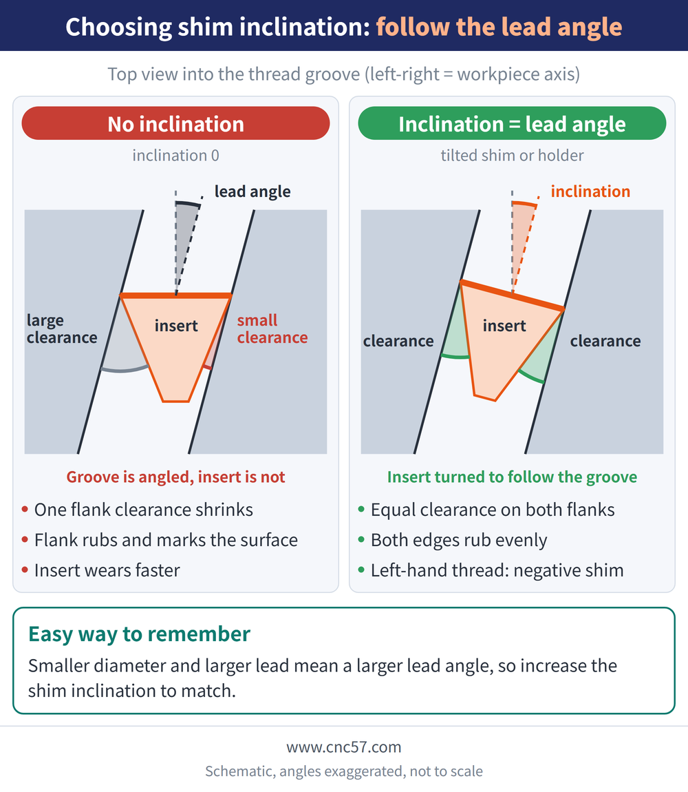
1. Lead Angle Basics
The lead angle is the helix angle formed by one revolution of the thread, related to pitch diameter (d), pitch (P) and, for multi-start threads, nP. The formulas are:
tan α = lead / (π × d) ; multi-start: tan α = nP / (π × d)
2. Lead Angle and Shim Selection
The shim angle must match the lead angle. As a rule, the larger the lead angle, the larger the shim angle; a very small lead angle can use a standard shim. Common shim angles:
| Shim angle | Lead |
|---|---|
| 0.5° | Small lead |
| 1° (Sandvik) / 1.5° (Mitsubishi) | Standard (brand-dependent, see note below) |
| 2.5° | Medium lead |
| 3.5° / 4.5° | Large lead |
⚠ Shim-angle numbering differs by brand: Sandvik uses 1° as the standard shim; Mitsubishi tool holders already carry a built-in 1.5° lead angle with a 0° standard shim tilt. These figures are for rough reference only — use the chart for your actual holder brand to avoid insert-flank interference.
Choosing the shim inclination: look at the difference
The point of changing shims is to bring the difference between the thread lead angle and the shim inclination into this range: 2.5° to 0.5° for 60° (55°) threads; 2° to 1° for 30° (29°) threads. For a lead angle of 2.2°:
60° thread: 2.2° − (2.5° to 0.5°) = −0.3° to 1.7°; any shim inclination in this range is suitable. The standard shim (0° tilt) can also cut, but the catalog recommends changing to a 1° shim.
30° thread: 2.2° − (2° to 1°) = 0.2° to 1.2°; a shim inclination in this range is suitable; pick the shim from the shim specification table.
3. Effect of a Wrong Lead Angle
A wrong shim angle causes insert flank interference, poor machined faces and fast wear — and in severe cases makes machining impossible. So confirm the lead angle by formula or chart before choosing a shim.
| Consequence | Note |
|---|---|
| Insert flank interference | Flank rubs the insert's relief face |
| Poor machined face | Rough flanks, off thread form |
| Fast wear / no machining | Severe interference destroys the insert fast |
4. Chart Use and Right/Left-Hand Threads
From the charts below, enter pitch (mm) and diameter (mm) to read the matching shim angle. Right- and left-hand threads take opposite shim polarity:
| Hand | Shim selection |
|---|---|
| Right-hand | Positive shim, common in general work |
| Left-hand | Negative shim, avoid the interference zone |
60°/55° threads: right-hand
| Pitch P (mm) | Not machinable | 4.5° | 3.5° | 2.5° | 1.5° (standard shim) | 0.5° |
|---|---|---|---|---|---|---|
| 0.5 | ≤ φ1.7 | φ1.7–φ2.3 | φ2.3–φ3.0 | φ3.0–φ4.6 | φ4.6–φ9.1 | ≥ φ9.1 |
| 0.75 | ≤ φ2.5 | φ2.5–φ3.4 | φ3.4–φ4.6 | φ4.6–φ6.8 | φ6.8–φ13.7 | ≥ φ13.7 |
| 1 | ≤ φ3.3 | φ3.3–φ4.6 | φ4.6–φ6.1 | φ6.1–φ9.1 | φ9.1–φ18.2 | ≥ φ18.2 |
| 1.25 | ≤ φ4.1 | φ4.1–φ5.7 | φ5.7–φ7.6 | φ7.6–φ11.4 | φ11.4–φ22.8 | ≥ φ22.8 |
| 1.5 | ≤ φ5.0 | φ5.0–φ6.8 | φ6.8–φ9.1 | φ9.1–φ13.7 | φ13.7–φ27.4 | ≥ φ27.4 |
| 1.75 | ≤ φ5.8 | φ5.8–φ8.0 | φ8.0–φ10.6 | φ10.6–φ16.0 | φ16.0–φ31.9 | ≥ φ31.9 |
| 2 | ≤ φ6.6 | φ6.6–φ9.1 | φ9.1–φ12.1 | φ12.1–φ18.2 | φ18.2–φ36.5 | ≥ φ36.5 |
| 2.5 | ≤ φ8.3 | φ8.3–φ11.4 | φ11.4–φ15.2 | φ15.2–φ22.8 | φ22.8–φ45.6 | ≥ φ45.6 |
| 3 | ≤ φ9.9 | φ9.9–φ13.7 | φ13.7–φ18.2 | φ18.2–φ27.3 | φ27.3–φ54.7 | ≥ φ54.7 |
| 3.5 | ≤ φ11.6 | φ11.6–φ15.9 | φ15.9–φ21.3 | φ21.3–φ31.9 | φ31.9–φ63.8 | ≥ φ63.8 |
| 4 | ≤ φ13.2 | φ13.2–φ18.2 | φ18.2–φ24.3 | φ24.3–φ36.5 | φ36.5–φ72.9 | ≥ φ72.9 |
| 4.5 | ≤ φ14.9 | φ14.9–φ20.5 | φ20.5–φ27.3 | φ27.3–φ41.0 | φ41.0–φ82.1 | ≥ φ82.1 |
| 5 | ≤ φ16.5 | φ16.5–φ22.8 | φ22.8–φ30.4 | φ30.4–φ45.6 | φ45.6–φ91.2 | ≥ φ91.2 |
60°/55° threads: left-hand
| Pitch P (mm) | Not machinable | −1.5° | −0.5° |
|---|---|---|---|
| 0.5 | ≤ φ3.6 | φ3.6–φ9.1 | ≥ φ9.1 |
| 0.75 | ≤ φ5.5 | φ5.5–φ13.7 | ≥ φ13.7 |
| 1 | ≤ φ7.3 | φ7.3–φ18.2 | ≥ φ18.2 |
| 1.25 | ≤ φ9.1 | φ9.1–φ22.8 | ≥ φ22.8 |
| 1.5 | ≤ φ10.9 | φ10.9–φ27.4 | ≥ φ27.4 |
| 1.75 | ≤ φ12.8 | φ12.8–φ31.9 | ≥ φ31.9 |
| 2 | ≤ φ14.6 | φ14.6–φ36.5 | ≥ φ36.5 |
| 2.5 | ≤ φ18.2 | φ18.2–φ45.6 | ≥ φ45.6 |
| 3 | ≤ φ21.9 | φ21.9–φ54.7 | ≥ φ54.7 |
| 3.5 | ≤ φ25.5 | φ25.5–φ63.8 | ≥ φ63.8 |
| 4 | ≤ φ29.2 | φ29.2–φ72.9 | ≥ φ72.9 |
| 4.5 | ≤ φ32.8 | φ32.8–φ82.1 | ≥ φ82.1 |
| 5 | ≤ φ36.5 | φ36.5–φ91.2 | ≥ φ91.2 |
Cells give the machined diameter φ (mm). (Arranged from the catalog values) Column headings are the combined holder plus shim inclination; the holder itself carries 1.5°, so the 1.5° column is the standard shim. Each column covers one band of lead angle: the smaller the diameter and the larger the pitch, the larger the inclination of the column you land in.
30°/29° threads: only the columns that differ
| Pitch P (mm) | RH: not machinable | RH: 4.5° | LH: not machinable | LH: −1.5° |
|---|---|---|---|---|
| 0.5 | ≤ φ1.8 | φ1.8–φ2.3 | ≤ φ4.6 | φ4.6–φ9.1 |
| 0.75 | ≤ φ2.7 | φ2.7–φ3.4 | ≤ φ6.8 | φ6.8–φ13.7 |
| 1 | ≤ φ3.6 | φ3.6–φ4.6 | ≤ φ9.1 | φ9.1–φ18.2 |
| 1.25 | ≤ φ4.5 | φ4.5–φ5.7 | ≤ φ11.4 | φ11.4–φ22.8 |
| 1.5 | ≤ φ5.5 | φ5.5–φ6.8 | ≤ φ13.7 | φ13.7–φ27.4 |
| 1.75 | ≤ φ6.4 | φ6.4–φ8.0 | ≤ φ16.0 | φ16.0–φ31.9 |
| 2 | ≤ φ7.3 | φ7.3–φ9.1 | ≤ φ18.2 | φ18.2–φ36.5 |
| 2.5 | ≤ φ9.1 | φ9.1–φ11.4 | ≤ φ22.8 | φ22.8–φ45.6 |
| 3 | ≤ φ10.9 | φ10.9–φ13.7 | ≤ φ27.3 | φ27.3–φ54.7 |
| 3.5 | ≤ φ12.7 | φ12.7–φ15.9 | ≤ φ31.9 | φ31.9–φ63.8 |
| 4 | ≤ φ14.6 | φ14.6–φ18.2 | ≤ φ36.5 | φ36.5–φ72.9 |
| 4.5 | ≤ φ16.4 | φ16.4–φ20.5 | ≤ φ41.0 | φ41.0–φ82.1 |
| 5 | ≤ φ18.2 | φ18.2–φ22.8 | ≤ φ45.6 | φ45.6–φ91.2 |
All other 30°/29° columns are the same as 60°/55°. Lead angle chart values are from the Mitsubishi general catalog, MMT series shim selection page (catalog page G012); for actual selection use the catalog for your own holder brand.
5. Insert Clearance Setting
Different thread angles need different insert clearance, and internal vs external work differs slightly (the table below is common reference values; follow the tool maker's spec):
| Thread angle | Internal clearance | External clearance |
|---|---|---|
| 60° | 8.8° | 5.8° |
| 55° | 7.9° | 5.2° |
| 30° | 4.1° | 2.7° |
| 29° | 4° | 2.6° |
Clearance values are from the Mitsubishi general catalog, MMT series page (catalog page G013), and are the insert clearances when mounted on that series of holders; for other brands use their own catalogs.
Threads with a smaller thread angle, such as trapezoidal and round threads, also leave smaller clearance on both insert flanks, so take extra care when choosing the shim.
6. Practical Advice
Confirm the shim by lead-angle calculation, avoid the interference zone, check insert wear regularly, and use a rigid tool holder — the four practical essentials. For thread-form standards, see the Thread Profile Guide; for infeed methods, see Thread Infeed Methods Explained.
FAQ
Q: How do I calculate the lead angle?
Lead angle is tan α = lead / (π × d), where lead equals pitch P for single-start and nP for multi-start, and d is the thread pitch (mean) diameter. After finding the angle, match it to a shim angle (0.5°, 1.5°, 2.5°, etc.).
Q: What happens with the wrong shim angle?
A shim angle that doesn't match the lead angle causes the insert's flank (relief face) to interfere with the thread flank, giving poor faces and fast wear — and can prevent the form entirely. The larger the lead angle, the larger the shim needed.
Q: Are right- and left-hand shims the same?
No. Right-hand threads generally use a positive shim; left-hand threads, with reversed helix, need a negative shim and care to avoid the interference zone. The wrong-hand shim causes interference and failure.
Q: How do I set insert clearance?
Insert clearance must suit the thread angle and lead angle, and internal vs external differ. For example, the Mitsubishi catalog lists 7.9° internal and 5.2° external for 55° threads, and 4° internal and 2.6° external for 29° threads (reference). Follow the tool maker's spec and lead-angle calculation.
Last updated: 2026-10-22
For the full reading guides on this topic, see Thread Machining: A Complete Reading Guide and Insert Selection: A Complete Reading Guide.









