
Measuring Spindle Dynamic Accuracy: Lissajous Curves and Spindle Speed
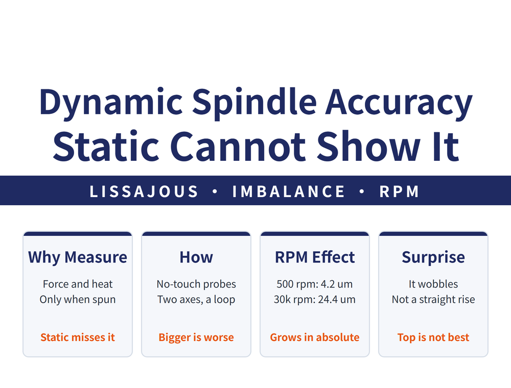
The accuracy measured on a stationary spindle is not the same thing as the accuracy it has once it is turning. Centrifugal force, vibration and heat only appear under rotation, and those are exactly what drive part size and tool life. Measured data shows radial error going from 4.2um at 500 rpm to 24.4um at 30,000. More interesting still, unbalance does not rise monotonically with speed but fluctuates, meaning certain speed bands behave particularly badly and maximum speed is not the most usable speed.
1. However Precise the Static Check, It Cannot See What Rotation Does
The core claim is short: because of centrifugal force, vibration and heat generated by rotation, dynamic accuracy can differ from static accuracy.
That is why machine acceptance cannot rest on measuring a stationary spindle. Centrifugal deformation, thermal growth and dynamic unbalance at high speed all appear only once the spindle is turning, and they act directly on dimensional accuracy and tool life. A static test sees none of it.
Turned the other way, once the dynamic behaviour is known you can pick more appropriate cutting conditions for the real job instead of backing off on instinct.
2. The Lissajous Curve: Two Directions of Runout in One Picture
The measurement uses a capacitive non contact displacement sensor to read displacement in X and Y at the same time, then feeds both signals into an oscilloscope where they overlay into a closed curve. That is the Lissajous curve.
Reading it is direct: the larger the extent of the curve, the larger the radial runout.
Non contact is the key. A contacting gauge cannot be used at high rotational speed, and contact itself changes the very state being measured.
3. Measured: What Happens to Radial Error as Speed Rises
| Speed (min⁻¹) | 500 | 10,000 | 30,000 |
|---|---|---|---|
| Radial error | 4.2 μm | 8.2 μm | 24.4 μm |
The proportions are worth noting: a 60 fold rise in speed gives only about a 5.8 fold rise in radial error, far less than the speed increase. But the absolute value grows clearly at ultra high speed, and 4.2um against 24.4um is a different class entirely for precision work.
That is the quantified reason to pay attention to dynamic accuracy figures when choosing ultra high speed spindles and holders. For choosing the holder interface, see [Spindle Taper Systems Overview: BT, HSK, Capto, SK, NT, CAT, MT].
4. 🔴 The Least Intuitive Part: Unbalance Does Not Simply Grow With Speed
Measuring unbalance with a field balancer across 0 to 30,000 min⁻¹ does not give a rising straight line:
| Speed (min⁻¹) | 5,000 | 10,000 | 15,000 | 20,000 | 25,000 | 30,000 |
|---|---|---|---|---|---|---|
| Unbalance (g·mm) | 8.5 | about 3.5 to 3.7 | 7.0 | 21.6 | 8.3 | 54.5 |
The trend falls, rises, falls again in the middle, then jumps at the end. In this example 20,000 and 30,000 are particularly poor, while around 10,000 is the best of the whole range.
A very usable conclusion: running at a speed where balance is good extends tool life and improves machining accuracy.
5. So Speed Selection Cannot Follow the Catalogue Maximum
That table overturns a common habit: buying a 30,000 rpm spindle and then running at 30,000. Certain speed bands behave particularly badly for balance, and those bands are not printed in any catalogue, because they depend on the combination of spindle, holder, tool and clamping. Only measurement finds them.
| Common habit | Problem | Suggestion |
|---|---|---|
| Set parameters from the top speed rating | May land exactly in the worst balance band | Check measured unbalance at that speed too |
| Only run a static runout check | Sees no centrifugal, thermal or dynamic effect | Add a dynamic check for high speed work |
| Blame the tool when life is poor | May be a balance problem at that speed | Try another speed band before judging |
That last row is worth remembering: the same tool giving very different life at different speeds is not necessarily a tool problem. Treating speed as a variable and trying once costs almost nothing.
6. Frequently Asked Questions (FAQ)
Q: Does an ordinary machine shop need to measure dynamic accuracy?
It depends on speed and tolerance. At ordinary speeds with generous tolerances a static check is usually enough; once you move into high or ultra high speed, or micrometre level accuracy, dynamic accuracy becomes the deciding factor.
Q: What if no capacitive displacement sensor is available?
Start with a field balancer and measure unbalance at several speeds, which still identifies the poorly behaved bands. Full Lissajous curve measurement is normally carried out by the machine supplier or a third party inspection service.
Q: Why does unbalance improve and then worsen mid range?
A rotating system has its own resonance behaviour, so amplitude grows approaching a resonance band and falls away from it, which produces fluctuation rather than a steady rise. The actual curve varies with the spindle and holder combination and has to be measured machine by machine.
Q: Can these figures be compared directly against my machine?
No. They are measured examples from one particular spindle and holder combination, offered to show trend and order of magnitude. Your own machine has to be measured, and both the shape of the curve and the position of its peaks will differ.
The figures here are measured examples from one particular spindle and holder combination, given to show trend and order of magnitude rather than as general specifications. Actual dynamic accuracy varies with machine, holder, tool and clamping, and should be measured machine by machine.
Last updated: 2026-09-14









