
Turning Tool Lead Angle Guide: Force, Chip & Tool Life
A turning tool's lead angle directly affects cutting-force distribution, chip thickness and tool life. A larger lead angle spreads the force over a longer edge and enlarges the nose angle, thinning the chip and raising nose strength and tool life, but raises the radial (back) force and can deflect slender parts; a smaller lead angle keeps the back force low for slender parts and finishing, at the cost of lower nose strength. Pairing lead angle, secondary angle and inclination angle correctly is key to stability and quality.
1. Lead Angle Basics
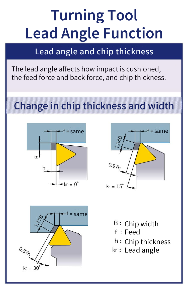
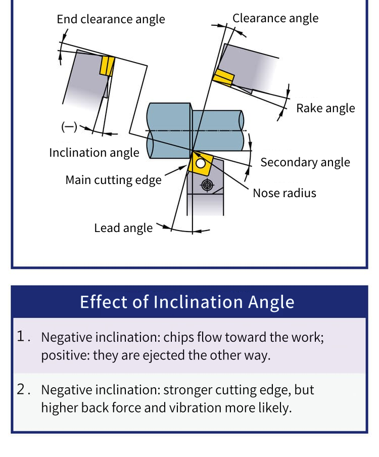
The lead angle is the angle between the main cutting edge and a line perpendicular to the feed direction — that is, 90° minus the entering angle (κr). It drives force distribution, chip thickness and width, tool life and workpiece deflection. Note that the figure above labels the lead angle itself as kr (kr = 0°, 15°, 30°); everywhere else in this article κr means the entering angle, and the two add up to 90°.
| Item | Content |
|---|---|
| Definition | Angle between main edge and the line perpendicular to feed (90° − entering angle) |
| Affects | Force distribution, chip thickness/width, tool life, deflection |
2. Lead Angle vs Chip Thickness and Force
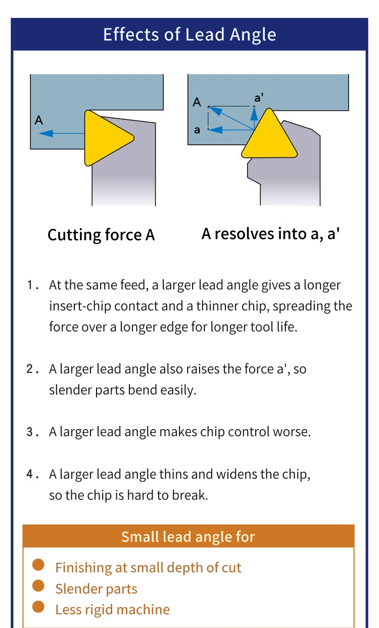
A larger lead angle thins the chip and widens it, spreading the load and extending tool life; but the force resolves into multiple directions, and a larger lead angle raises the radial (back) force, deflecting slender parts.
| Lead angle change | Effect |
|---|---|
| Larger lead angle | Thinner/wider chip, spread load, longer tool life |
| Larger lead angle (force) | Higher back force, slender parts deflect |
3. Stability and Application
A large lead angle reduces local tool load and raises life, but increases side force and possible vibration. Choose by operation type.
| Lead angle | Pros / cons | Best for |
|---|---|---|
| Large | Larger nose angle and higher nose strength, less local load, longer life; more side force, possible vibration | Hard workpieces or high cutting temperature, roughing of large-diameter parts, rigid machine |
| Small | Lower back force, less deflection of slender parts; but smaller nose angle and lower nose strength | Finishing at small depth of cut, slender parts, less rigid machine |
As a starting point, the table below gives reference entering angles for carbide turning tools by operation and machine rigidity; the lead angle is converted as 90° − entering angle (negative when the entering angle is above 90°).
| Operation | Machine rigidity | Entering angle κr | Lead angle (90° − κr) |
|---|---|---|---|
| Rough turning (no plunge from the middle) | Good | 45°, 60°, 75° | 45°, 30°, 15° |
| Rough turning (no plunge from the middle) | Poor | 65°, 70°, 90° | 25°, 20°, 0° |
| Slender shafts, thin-walled parts | — | 90°, 93° | 0°, −3° |
| Finish turning (no plunge from the middle) | Good | 45° | 45° |
| Finish turning (no plunge from the middle) | Poor | 60°, 75° | 30°, 15° |
| Chilled cast iron, hardened steel | — | 10°~30° | 60°~80° |
| Plunging in from the middle of the part | — | 45°~60° | 30°~45° |
| Parting and grooving tools | — | 60°~90° | 0°~30° |
The finishing rows take a larger lead angle to keep surface roughness down; when turning slender parts or on a less rigid machine, keeping the radial force down comes first and the lead angle stays small (see the slender-shaft row).
4. Secondary Angle
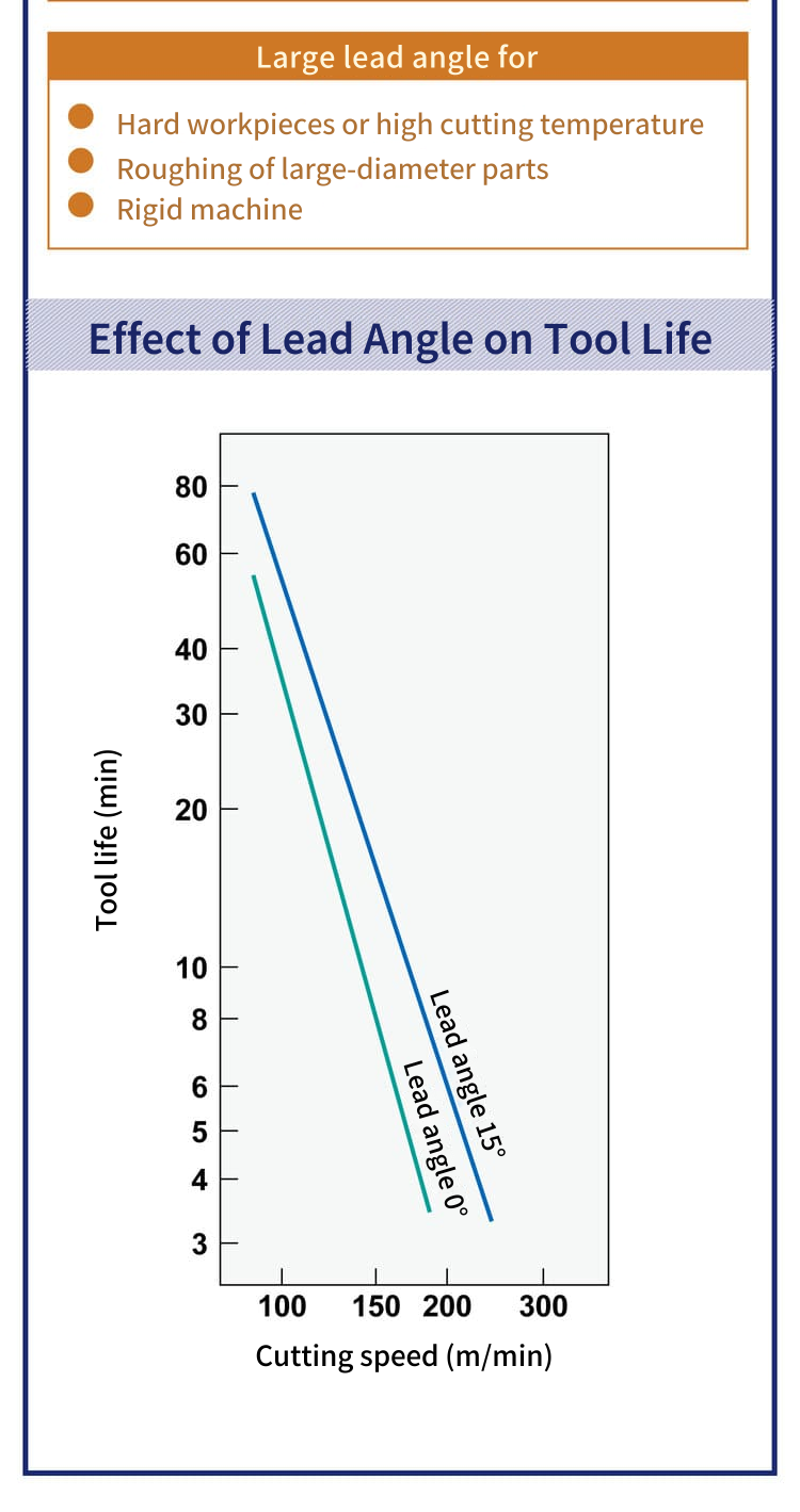
The secondary (end cutting edge) angle avoids interference with the finished surface, typically about 5°–15°. A small secondary angle is stronger but vibrates more; a large one gives better accuracy.
On roughing versus finishing, two sources point in opposite directions because they put different things first. The tool maker’s technical data behind this article’s figures puts vibration first: a small secondary angle raises the back force and invites chatter, so it recommends small for roughing and large for finishing. The same handbook as the entering-angle table above puts surface finish first: a larger secondary angle leaves higher feed marks and a rougher surface, so it gives 0°–5° for finish turning, smaller than the 5°–15° for roughing. On a rigid, chatter-free setup, a small secondary angle in finishing keeps roughness down; once vibration appears, increase it first.
| Item | Content |
|---|---|
| Function | Avoid interference with the finished surface |
| Typical range | About 5°–15° |
| Effect | Small → strong but vibrates; large → better accuracy |
| Guideline | Two views: vibration first → small for roughing, large for finishing; surface finish first → 0°–5° for finish turning, smaller than roughing |
5. Inclination Angle
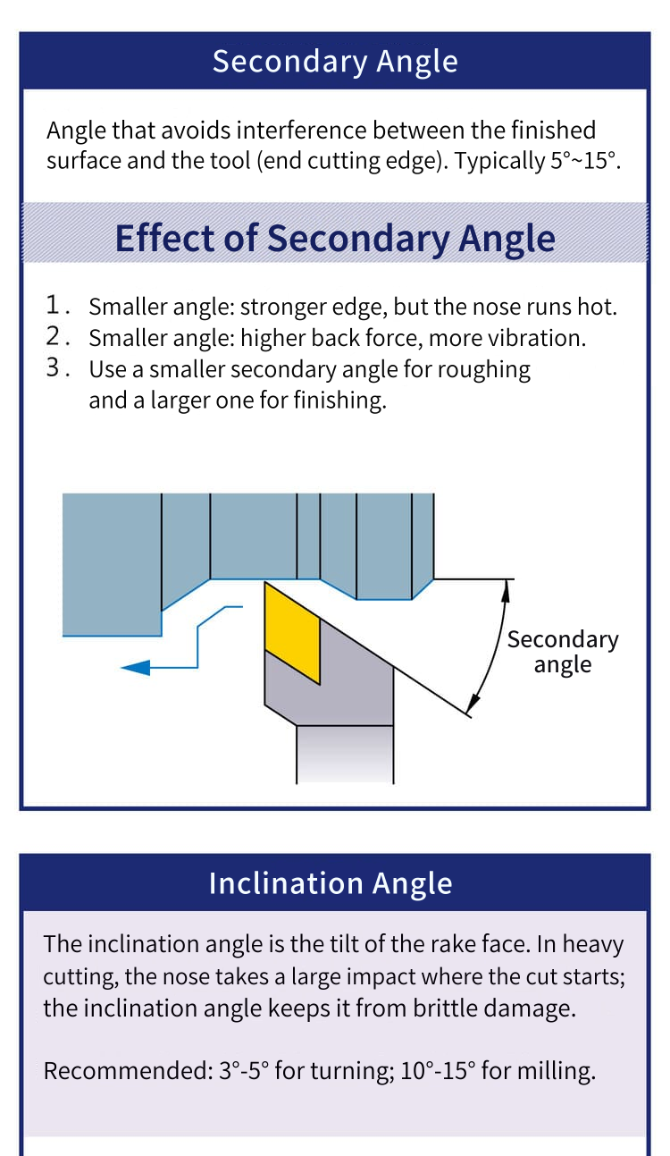
The inclination angle is the tilt of the rake face, controlling chip flow and spreading cutting impact. A positive inclination sends the chip away from the part (good evacuation, lower strength); a negative one keeps the chip near the part (high strength, more vibration).
| Inclination | Chip flow | Trait |
|---|---|---|
| Positive | Chip away from part | Good evacuation, lower strength |
| Negative | Chip toward part | High strength, more vibration |
6. Overall Geometry Pairing
Lead angle, secondary angle and inclination angle are the three key angles. The best strategy balances cutting force against tool strength, controls chip flow, and reduces vibration and deflection to balance efficiency and quality.
7. Common Problems and Fixes
Poor angle setup shows up as deflection, wear, vibration or evacuation issues. Calculate actual speed and feed from your material and machine — see the Turning Machining Formulas.
| Problem | Cause | Fix |
|---|---|---|
| Workpiece deflection | Lead angle too large | Reduce lead angle |
| Fast tool wear | Concentrated load | Increase lead angle |
| Vibration | Secondary angle too small | Increase secondary angle |
| Poor evacuation | Wrong inclination | Adjust inclination |
8. Optimization and Engineering Focus
Optimize the lead-angle setup in tool design, match feed and depth in conditions, and raise rigidity in the machine setup. With lead, secondary and inclination angles as core parameters, the control goals are to reduce force concentration, extend tool life and improve stability — for stable quality, less tool loss and higher productivity. For insert grade selection, see the ISO Turning Insert Guide.
FAQ
Q: Is a larger lead angle always better?
Not necessarily. A large lead angle thins the chip, spreads the load, enlarges the nose angle for a stronger tip and extends tool life, and suits harder workpieces or high cutting temperatures, roughing of large-diameter parts and rigid machines; but back and side forces rise, so slender parts deflect and vibration becomes more likely. A small lead angle suits finishing at small depth of cut, slender parts and less rigid machines, where keeping the back force down comes first, at the cost of lower nose strength.
Q: What if a slender part deflects?
Deflection of slender parts usually comes from too large a lead angle raising back force. Reduce the lead angle to cut radial thrust, raise clamping and machine rigidity, and if needed split the cut or add tailstock support.
Q: What does the secondary angle do?
The secondary angle (about 5°–15°) avoids interference with the finished surface. A small one gives a stronger nose but vibrates more; a large one gives better accuracy. For roughing versus finishing there are two views: with vibration as the priority, use small for roughing and large for finishing; with surface finish as the priority, finish turning takes 0°–5°, smaller than roughing. On a rigid, chatter-free setup you can go small; if vibration appears, increase it.
Q: Positive or negative inclination?
Positive inclination sends chips away and evacuates well but lowers edge strength — good for general and finishing; negative inclination keeps chips near the part with a stronger, impact-resistant edge but more vibration — good for heavy and interrupted cutting.
For the full reading guides on this topic, see Tool Life and Wear: A Complete Reading Guide and Vibration and Chatter: A Complete Reading Guide.
For the full reading guide on this topic, see Turning: The Complete Guide.
Published: 2026-03-25 | Last updated: 2026-10-21









