
Centerless Grinding: Four Methods, Regulating Wheel and Blade Setup, Defects
Centerless grinding uses no centres and no centre holes—the part rides on a blade between the grinding wheel and the regulating wheel. The locating principle is nothing like centre-type cylindrical grinding, so neither the settings nor the defects carry over. This covers the four methods, why the regulating wheel must be a hyperboloid, how to set blade angle and work centre height, and how to trace defects.
1. Locating without centres
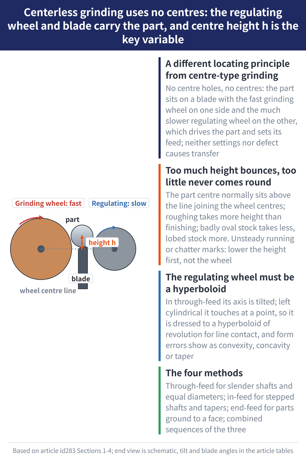
Centerless grinding drills no centre holes and uses no centres. The part sits on a work rest blade with the fast grinding wheel on one side and the much slower regulating wheel on the other; the regulating wheel drives the part and sets how it feeds along. The part centre normally sits a little above the line joining the two wheel centres, and that height (h) is the most important variable in the whole process.
Because the locating principle differs, neither settings nor defect causes transfer from centre-type cylindrical grinding. For that method, see the three grinding operations.
2. The four methods
| Method | Suits | Key points |
|---|---|---|
| Through-feed | Long slender shafts, equal-diameter parts, rollers | Part passes axially through; slender shafts take about 1°30′–2°30′ tilt |
| In-feed | Stepped shafts, external tapers, pointed parts | Part rests against a stop and the wheel feeds in; stepped shafts 15′–30′ |
| End-feed | Parts ground to a face (stepped shafts, bushes, taper pins) | Through-feed first, then grind to a stop bar |
| Combined | Radiused parts, faces square to the diameter | Sequences of the above, e.g. in-feed then through-feed then end-feed |
A through-feed grinding wheel is not a plain cylinder: it must cover entry, roughing, finishing (spark-out) and exit zones along its width—deeper cuts want longer entry and roughing zones, light cuts want a longer finishing zone.
3. The regulating wheel must be a hyperboloid
In through-feed the regulating wheel axis tilts in the vertical plane. Left cylindrical, it only touches the part at a point; to get line contact along the whole length it must be dressed to a hyperboloid of revolution. An error in that form shows up as convexity, concavity or taper on the part, and the part centre wanders and chatters.
| Case | Tilt angle |
|---|---|
| Through-feed roughing | 2°–6° |
| Through-feed finishing | 1°–2° |
| Long parts | 0.5°–1.5° |
| In-feed | 0°–0.5° |
When dressing, the contact point on the dresser shifts with the work centre height, by an amount set by the regulating wheel to part diameter ratio; the dresser slide swings through an angle equal to or slightly less than the wheel tilt.
4. Blade angle and work centre height
Blade angle runs 20°–60°, with 20°, 30° and 45° the usual choices: lower for roughing or larger diameters, higher for finishing or small diameters; for very slender bar with the centre below the wheel centre, use 0° for blade rigidity. Blade thickness is normally 1.5–2mm under the part diameter; for in-feed, a blade 5–10mm longer than the part is enough.
Too much height and the part bounces periodically; too little and it never comes round. If the part runs unsteadily or shows chatter marks, lower the height and regrind before reaching for a different wheel.
| Situation | Height direction |
|---|---|
| Roughing vs finishing | Roughing takes more height than finishing |
| Incoming part badly oval | Lower |
| Incoming part badly lobed | Higher; if both, take lobing out high then finish low |
| Thin-wall sleeve / slender bar | Higher for sleeves, lower for slender bar |
5. Tracing defects
| Defect | Look here first |
|---|---|
| Out of round | Regulating wheel not trued, bearing clearance, slack belt, dull wheel |
| Lobing | Work centre too low, blade too thin or angle too steep, wheel out of balance |
| Taper | Guides not parallel to the regulating wheel line, tapered wheel, bent blade |
| Chatter marks | Wheel out of balance, centre too high, wheel too hard or too fine |
| Size scatter | Uneven incoming stock, dress and compensation amounts not matched |
Centerless grinding removes a lot and makes a lot of heat, so flood alone will not do: feed the fluid through a nozzle that picks up wheel speed and forces it into the zone, or use an air deflector to create a partial vacuum ahead of the nozzle, with a baffle to block airflow and stop splashing. For choosing the fluid, see choosing a grinding fluid.
6. Frequently Asked Questions (FAQ)
Q: Why must the regulating wheel be a hyperboloid?
Because its axis is tilted. A plain cylinder touches the part at a single point; dressed to a hyperboloid of revolution it contacts along the full length. Form errors there turn into convexity, concavity, taper and chatter.
Q: Chatter marks—what do I change first?
Lower the work centre height. Too much height makes the part bounce periodically and leave chatter marks. Only then check wheel balance, blade rigidity and wheel grade and grit.
Q: The part is both lobed and oval—now what?
Split it into two passes. Lobing wants a higher work centre and ovality a lower one, so take the lobing out with the centre high, then drop it and finish to remove the ovality.
Q: Through-feed or in-feed?
It follows the part shape. Equal-diameter slender shafts and rollers pass straight through, so through-feed suits volume work. Anything with a step, a taper or a face to grind to needs in-feed, with the tilt angle brought near zero.
This article is part of Grinding Wheels and Machines: The Complete Guide - Reading the Wheel, Mounting It, Dressing It, and Tracing Defects; that guide shows how the whole topic fits together.
Published: 2026-08-16|Updated: 2026-08-16









