
Cylindrical, Internal and Surface Grinding: Workholding, Motions and Grinding Data
Cylindrical, internal and surface grinding are the three everyday operations. They use a different face of the wheel, hold the part differently and allow very different grinding data—an internal spindle runs more than ten times the speed of a cylindrical one, and surface grinding adds the question of whether the chuck can even hold the part. This lines up all three.
1. Telling the three apart
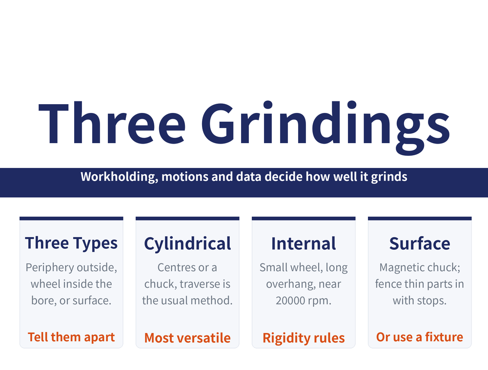
The difference is which face of the wheel cuts, and how the part moves:
| Operation | Wheel face used | Most used method |
|---|---|---|
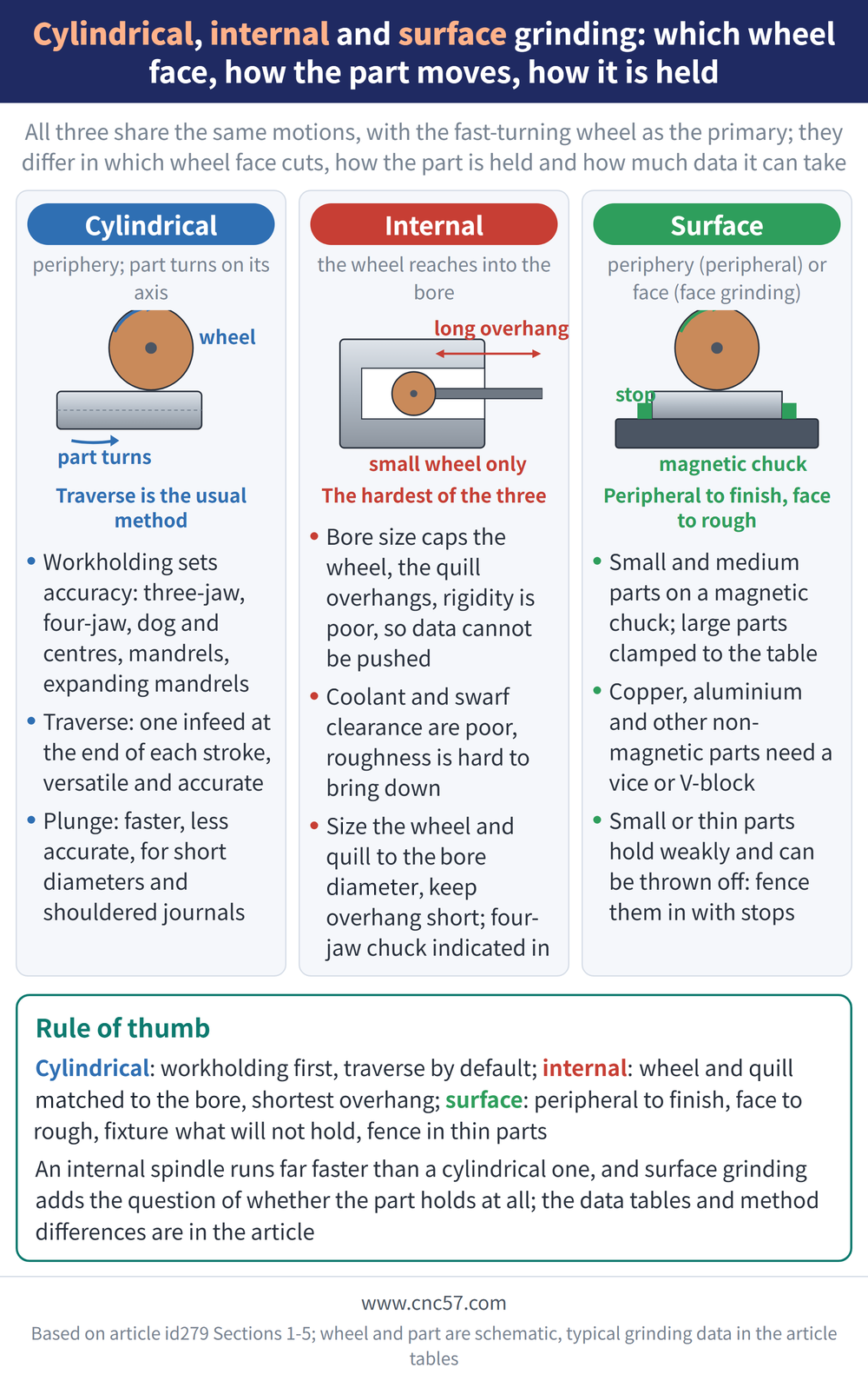
| Cylindrical | Periphery; part turns on its own axis | Traverse (most widely used) |
| Internal | Periphery; wheel reaches into the bore | Traverse (most widely used) |
| Surface | Periphery (peripheral) or face (face grinding) | Peripheral to finish, face to rough |
All three share the same set of motions: the wheel spinning is the primary motion, plus the part's rotary feed, the longitudinal feed and the wheel's infeed. For reading the wheel itself, see Reading a Grinding Wheel Marking.
2. Cylindrical grinding: how the part is held
Accuracy starts with workholding. The common options:
| Method | Where it fits |
|---|---|
| Three-jaw self-centring chuck | Centres well but grips lightly; small to medium regular parts, not too long |
| Four-jaw independent chuck | Strong grip, takes irregular parts, but must be indicated in |
| Dog and centres | Shafts; centres must run true to the spindle, centre holes matter |
| Internal / external crown centres | Bored parts, or shafts with no centre holes; just clamp up and grind |
| Plain, taper or spline mandrel | Locating on the bore; taper is more accurate, spline must not work loose |
| Expanding mandrel | Thin-walled parts; the expanding sleeve removes clamping distortion |
Slender shafts lack rigidity, so they deflect away from the wheel and bend elastically, and come out barrelled, waisted or tapered. When the part is long and the accuracy tight, add steady rests: how many depends on the part's length and diameter, the support centre must sit on the part's axis, and the band each rest bears on is ground first or fitted with a dedicated sleeve. The alternative without steady rests is to dress a groove about two thirds of the wheel width into the middle of the wheel face and run it with a spring-loaded tailstock centre. For the shop rules on no plunge grinding and aligning the steady rest, see Grinding Practice Rules: 7 on Workholding, 4 on the Wheel and 11 on Operation; for the speed ratio in high speed grinding, see High Speed Grinding Wheels and Parameters: Five Selection Items, the k Value Chart and a Parameter Table.
3. Cylindrical grinding: data, traverse and plunge
| Item | Typical range |
|---|---|
| Wheel speed | 30–50 m/s |
| Work speed | 13–26 m/min; higher for roughing, lower for finishing |
| Longitudinal feed | (0.2–0.8) × wheel width |
| Infeed | Very small, about 0.005–0.05mm |
These are handbook typical ranges; take the actual figures from your machine and wheel specification.
Traverse grinding: the part turns and reciprocates with the table, and the wheel takes a small infeed at the end of each stroke; near size (about 0.005–0.01mm left) infeed stops and it sparks out. Versatile and accurate but slower, so it suits one-off and small-batch work and finishing.
Plunge grinding: no longitudinal feed at all—the wheel feeds in slowly until the stock is gone. Fast, but less accurate and rougher; it suits short cylindrical faces and journals with a shoulder each side.
For parts between centres that come out of round, check the centre holes first: see Out of Round on the Cylindrical Grinder? Check the Centre Holes First. For reversing and backing off beside a shoulder, see Grinding a Stepped Shaft: Reversal Position, Wheel Backoff and Radiused Corners; for grinding a taper, see Choosing a Taper Grinding Method: Cone Angle and Part Length Decide.
4. Internal grinding: built-in limits and typical data
Bore size caps the wheel diameter, and the quill reaches inside with a long overhang and poor rigidity, while coolant and swarf clearance are poor too, so grinding data cannot be pushed. Bigger is not always better for the wheel and quill: take a larger ratio for small bores and a smaller ratio for large bores, and keep the overhang as short as the job allows; for the four built-in limits and how to choose, see Why Internal Grinding Is the Hardest: Get the Wheel and the Quill Right First.
| Item | Typical internal value |
|---|---|
| Wheel speed | 15–25 m/s; internal spindle around 20000 rpm |
| Work speed | 15–25 m/min |
| Longitudinal feed rate | Roughing 1.5–2.5, finishing 0.5–1.5 m/min |
| Infeed | Roughing 0.01–0.03, finishing 0.002–0.01mm |
Also handbook typical ranges; confirm against your machine and wheel specification.
Parts locate on the outside diameter and a face, most often in a four-jaw independent chuck indicated in. The wheel turns the opposite way to cylindrical grinding, and contact is either behind (internal grinder) or in front (universal cylindrical grinder). Two correction factors exist here that cylindrical grinding does not have: wheel-to-bore diameter ratio and ground-length-to-bore ratio—the worse the ratio, the more the depth of cut must come down. For blind bores, keyways and thin sleeves, see Blind Bores, Keyways and Thin Sleeves: Internal Grinding Countermeasures.
5. Surface grinding: chuck, peripheral and face
Small and medium parts sit on a magnetic chuck; large parts clamp straight to the table T-slots with plates and angle plates. Copper, aluminium and other non-magnetic parts will not hold, so add a vice, V-block or simple fixture on the chuck or table.
⚠ Small or thin parts sit on too little area, hold weakly, and the grinding force can throw them off the chuck—always fence these in with stops.
| Compare | Peripheral | Face |
|---|---|---|
| Contact and swarf | Small area, good clearance and cooling | Large area, coolant struggles to reach |
| Distortion and burn | Little distortion | More heat, burns readily |
| Accuracy / output | More accurate, slower | Rigid, takes heavy data, faster |
| Fits | Finishing | Roughing |
Longitudinal feed rises with wheel width, and the finishing feed should never exceed the roughing value. For vertical and angled faces, see Surface Grinders Only Grind Flat: Holding and Aligning Vertical and Angled Faces; for thin parts that bow once released, see Thin Parts Bow After Grinding: Separate Thermal Distortion from Clamping Distortion. For tracing a bad part back to its cause, see Grinding Defects: Tracing the Cause.
6. Frequently Asked Questions (FAQ)
Q: Traverse or plunge?
Use traverse when you want accuracy, or one wheel to cover parts of different lengths—it is the usual choice for one-offs, small batches and finishing. Use plunge on short diameters or journals with a shoulder each side; it is faster but less accurate and rougher.
Q: Why does an internal spindle run at 20000 rpm?
The bore caps the wheel diameter, and a small wheel still needs enough surface speed, so the rpm has to rise. A cylindrical grinder with a new wheel runs about 1660 rpm against roughly 20000 rpm on an internal spindle.
Q: What should I watch when surface grinding thin parts?
A thin part sits on little area and holds weakly, so grinding force can throw it off the chuck—fence it in with stops. Copper and aluminium will not hold magnetically at all and need a fixture.
Q: Peripheral or face grinding?
Peripheral has a small contact area, clears swarf and coolant well and holds accuracy, so it suits finishing. Face grinding has a large contact area, is rigid and takes heavy data for output, but burns easily, so it suits roughing.
This article is part of Grinding Wheels and Machines: The Complete Guide - Reading the Wheel, Mounting It, Dressing It, and Tracing Defects; that guide shows how the whole topic fits together.
Published: 2026-08-16|Updated: 2026-10-24









