
How Much Clamping Force Do You Need: Cutting Force, Bolt Force and Two Worked Examples
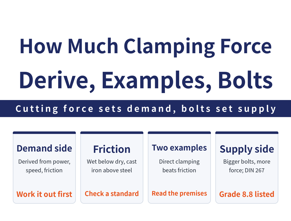
How much clamping force a part needs is calculated, not felt. The calculation has two sides: the demand side works back from the cutting force to the minimum clamping force required, and the supply side asks how much force a bolt or clamping element can actually deliver. This guide gives the formulas for both sides, two worked examples, and the one variable that is often mishandled — why the static friction coefficient should not be taken as a single number.
1. First Fix the Frame: Clamping Force Has a Floor, Not a Target
The purpose of clamping force is simple: hold the part securely, with a magnitude at least large enough to absorb the cutting force the machine applies to it. That sentence defines a floor, not a target value.
So the design order is fixed: estimate the cutting force first, then work back to the clamping force required. Below the floor the part shifts and the tool deflects; above it, the extra force adds no stability and turns into elastic deformation of the part. For that side of the problem, see Why Vise Clamping Distorts the Workpiece. This article is about calculating the floor.
2. Demand Side: Working Back From Cutting Power to Fsp
The demand side needs four quantities: cutting power P (kW), drive efficiency η (spindle motor to tool), cutting speed Vc (m/min) and cutting force Fs (kN). They relate as P×η = (Fs×Vc)/60.
The clamping force Fsp resists the cutting force through friction, so the condition is Fsp×μ ≥ Fs. Substituting gives:
Fsp = (P×η×60) / (Vc×μ) kN (μ = static friction coefficient)
Only μ has to come from outside the formula. The smaller μ is, the more clamping force the same cutting force demands — which is why it gets its own section.
3. Static Friction Coefficient: Direction First, Values From a Standard Table
μ is not a constant. It moves with the cutting environment and the material pairing:
| Variable | Direction of the relationship | Effect on Fsp |
|---|---|---|
| Cutting environment | Wet is lower than dry (cutting fluid enters the contact face) | Wet cutting needs more clamping force |
| Material pairing | Cast iron on cast iron > cast iron on steel > steel on steel | Steel on steel needs more clamping force |
| Where to get values | Fixture supplier data or a standard table | Confirm the dry or wet condition at the same time |
This article does not list coefficient values. The set available comes from measurements under a single condition, and it changes with surface condition and jaw material, so running a safety factor off one number carries too much risk. Ask your fixture supplier for the coefficient of your material pairing, or take it from a standard table.
4. Worked Example 1: Force Direction Changes the Requirement
Both examples below are arithmetic under their own stated premises. They are not general specifications and change as soon as the premises change — read them for the trend.
Premises: spindle power 80 kW, cutting force Fs = 60 kN, cutter diameter 290 mm (16 teeth), depth of cut 15 mm, width of cut 240 mm, workpiece strength 130 kgf/mm², lever arm ratio 850:750.
Method 2 (swing cylinder, direct clamping): Fsp2×750 = Fs×850 → Fsp2 = 60×850/750 = 68 kN (about 6.8 tonnes)
Method 1 (block cylinder, force transmitted through friction) is governed by Fr×750 = Fs×850 with Fr = Fsp1×μ. There is no reliable μ for that clamping face, so no figure is calculated there and this article does not supply one. To use the relation, establish the coefficient for your own contact pair first.
The conclusion is direct: clamping in a direction that acts directly is less demanding than relying on friction. The friction path multiplies by a coefficient below 1, so the same effect needs a larger clamp.
5. Worked Example 2: Contact Condition at the Clamp Point
The second example compares one clamping force under two contact conditions. Premises: Fe = 20,000 N, μ₀ = 0.15, contact angle α = 45°, tanρ = 0.15 → friction angle ρ = 8.5°.
Case 1 (deforming force at the locating point): Fsp = Fe×tan(α+ρ) = 20,000×tan(53.5°) = 20,000×1.35 = 27,000 N
Case 2 (clamp point bites into the part): Fsp = Fe×tan(α+2ρ) = 20,000×tan(62°) = 20,000×1.88 = 37,600 N
The two expressions differ only in whether the angle term carries ρ or 2ρ. A biting clamp needs noticeably more force, and more force brings back the distortion problem from section 1. Same caution: these figures are tied to the premises above and do not hold once the angle or coefficient changes.
6. Supply Side: How Much a Bolt Delivers
Once the requirement is known, check that the hardware can supply it. The most common manual source is a bolt, where the clamping force Fs follows from the wrench input and the thread geometry:
Fs = (Fh×L) / (R×tan(α+φ))
Fh = tightening force at the wrench | L = wrench length | R = pitch circle radius of the thread | α = helix angle | φ = friction angle = tan⁻¹(friction coefficient)
Rather than calculating every bolt, look the value up. The table below is for grade 8.8 bolts to DIN 267 section 3, used to 33.3% of tensile strength (transcribed from Jig and Fixture Application Practice, chapter 1, pp. 47–48):
| Bolt size | Clamping force (kN) | Approx. (kgf) |
|---|---|---|
| M5 | 3.1 | about 316 |
| M6 | 4.4 | about 449 |
| M8 | 8.0 | about 816 |
| M10 | 12.6 | about 1,286 |
| M12 | 18.5 | about 1,887 |
Conversion uses 1 kN = 1,000 N ≈ 102 kgf. The table runs only M5 through M12; M14 and above are not listed and are not extrapolated here — for larger sizes consult DIN 267 itself or the bolt supplier. The trend is clear enough: a larger bolt gives more clamping force, but grade and tightening torque are variables too, so a change of grade means a different set of values.
7. Putting the Two Sides Together
In practice the sequence has three steps: calculate the requirement Fsp with the formula in section 2, check what the hardware supplies using section 6, then confirm the part itself can take that force.
The third step is the one most often skipped. Sufficient supply does not mean you should clamp to the limit — the ceiling comes from the rigidity of the part and the clamp position, not from the bolt. For how the whole fixture is put together, see What Is a Jig and Fixture.
8. Frequently Asked Questions (FAQ)
Q: Can I just take a fixed multiple of the cutting force?
Not advisable. That multiple is effectively 1/μ, and μ moves with the material pairing and with dry or wet cutting, so a fixed multiple treats a variable as a constant. Put the coefficient for your own conditions into Fsp = (P×η×60)/(Vc×μ) instead.
Q: Why does this article not give friction coefficient values?
The available coefficients come from measurements under a single condition and shift with surface condition and jaw material, so using them in a safety factor carries too much risk. Only the direction is given here: wet is lower than dry, and cast iron on cast iron exceeds cast iron on steel, which exceeds steel on steel. Take actual values from fixture supplier data or a standard table.
Q: Can I apply the 27,000 N and 37,600 N figures to my own part?
No. Those are worked-example arithmetic under Fe = 20,000 N, α = 45° and ρ = 8.5°, not general specifications. What transfers is the trend: a biting clamp needs noticeably more force. Recalculate with your own angles and coefficient.
Q: Where do I find clamping force for M14 and larger bolts?
The table covers M5 through M12 only, and the listed values must not be extrapolated upward. Consult DIN 267 itself, or ask the bolt supplier for clamping force data at the grade and tightening condition you are using.
This article is part of Workholding and Fixtures: The Complete Guide - Locate First, Then Clamp; How Much Force and Where It Comes From; that guide shows how the whole topic fits together.
Published: 2026-08-28 | Last updated: 2026-08-28









