
What Is a Jig and Fixture: Locating, Clamping, Guiding, and How They Are Classified
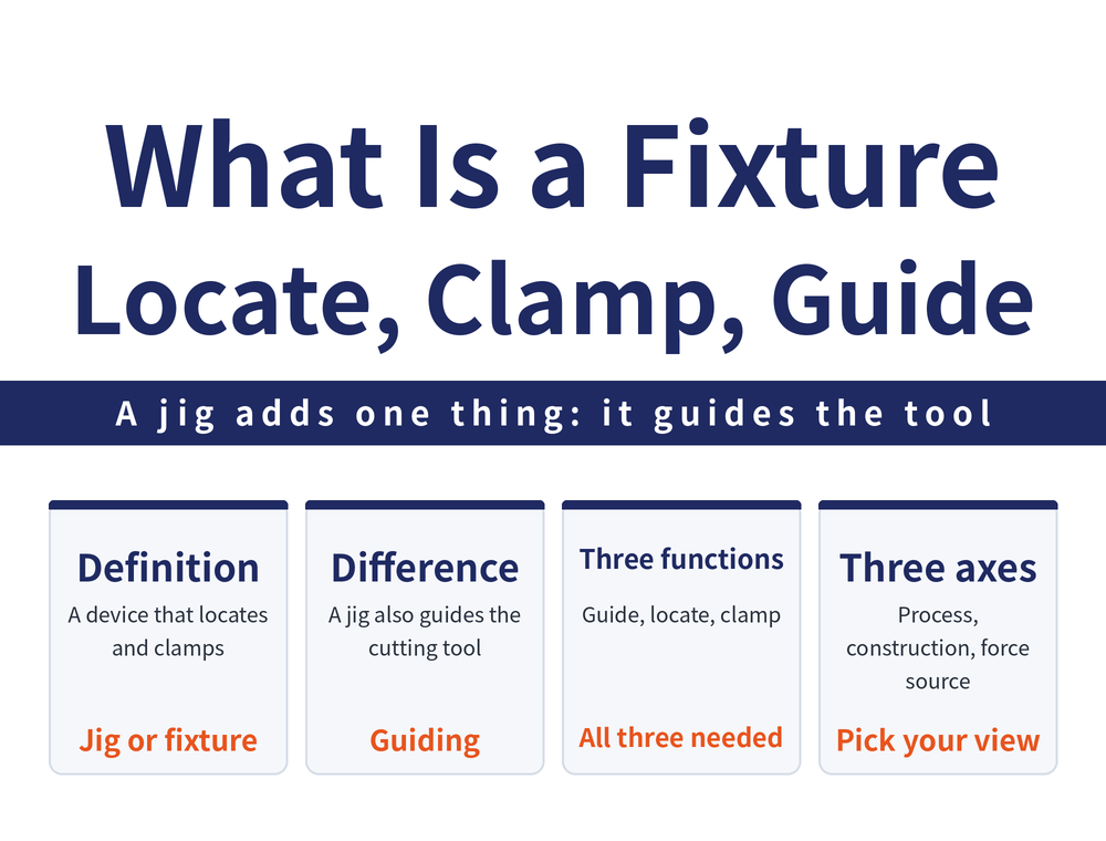
A jig or fixture is the device that locates a workpiece and clamps it to the machine tool. Jigs and fixtures differ by exactly one function — tool guiding — and they are classified on three axes: machining method, construction type, and source of clamping force. This guide covers the definition, the three core functions, the three classification axes, and the drawing vocabulary of three points and four colours.
1. What a Jig or Fixture Is: The Device That Holds the Part
Cutting applies a force to the workpiece, and the part must be held securely on the machine tool so that force can be absorbed and the cut completed. The device that locates and clamps the workpiece is called a jig or fixture (Jigs & Fixture).
It takes no part in the cut, yet it decides whether the cut stays stable.
2. Jig or Fixture: The Difference Is Tool Guiding
In the original definition the two differ by exactly one thing: whether tool guiding is included.
A fixture provides two functions, locating and clamping the workpiece. A jig provides those and adds a tool guiding function on top.
CNC machining fixtures can already dispense with tool guiding, so the fixture functions alone — locating plus clamping — are enough. That is why "fixture" gradually replaced "jig" as the general term in the CNC era.
3. Three Core Functions: Guiding, Locating, Clamping
A jig or fixture must at minimum be able to guide, locate and clamp the workpiece. Four further functions should be considered during design:
| Level | Item |
|---|---|
| Basic function | Guide the workpiece |
| Basic function | Locate the workpiece |
| Basic function | Clamp the workpiece |
| Extended function | Prevent operator error and inconsistency |
| Extended function | Keep loading and unloading smooth |
| Extended function | Make chips easy to clear |
| Extended function | Account for operator safety |
4. Axis 1: By Machining Method
Jigs and fixtures are classified on three independent axes, and one fixture is described by all three at once — for example, "a modular manual fixture for a milling machine".
The first axis is the machining method. Machining divides broadly into turning, milling, drilling, tapping, EDM, grinding and gear cutting; beyond machining, they are also used in assembly and inspection.
5. Axis 2: By Construction Type
| Type | Definition | Where it fits |
|---|---|---|
| General-purpose jig or fixture | Standard workholding elements such as vises, three-jaw chucks and universal fixture sets | Regular part shapes (square or round) |
| Modular jig or fixture | Also called a modular fixture system; built from a standard base plate plus locating and clamping components, and can be taken apart for another part | High-mix low-volume or prototype work; fast build-up and irregular part shapes |
| Dedicated jig or fixture | A fixture designed for one specific part | Usually a mass-production machining line |
6. Axis 3: By Source of Clamping Force
| Type | Definition |
|---|---|
| Manual fixture | The operator tightens the part with a tool, for example with screws or quick clamps |
| Automated fixture | Clamps the part automatically using electromagnetic force, pneumatics, hydraulics, spring force and similar means |
The three axes are independent: a general-purpose fixture can be manual or automated, and so can a dedicated one.
7. Reading a Fixture Drawing: Three Points and Four Colours
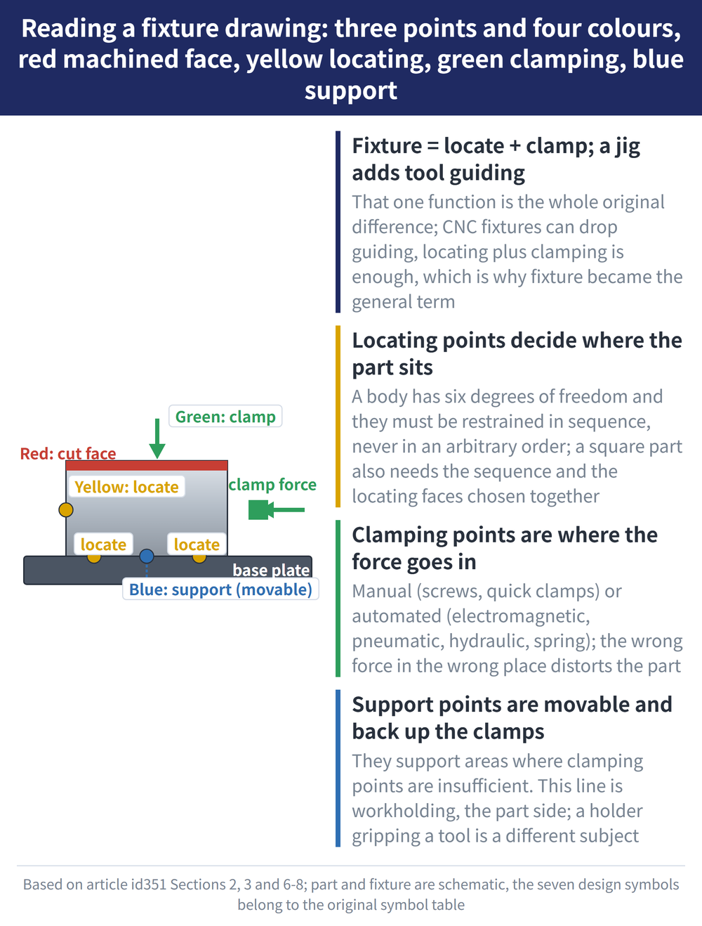
Fixture drawings use three fixed terms. A locating point is the point that determines where the part sits in the fixture. A clamping point is where clamping force is applied. A support point supports areas of the part where clamping points are insufficient, and it is a movable point. Machining drawings mark them by colour:
| Marked item | Colour |
|---|---|
| Surface to be machined | Red |
| Locating point | Yellow |
| Clamping point | Green |
| Support point | Blue |
There are also seven classes of design symbol (locating, clamping, locating and clamping, support, support and clamping, position adapting to the part shape, and two-direction clamping). The symbols themselves are engineering drawing graphics; the text version of the source cannot reproduce their appearance, so this article neither shows nor describes them. Take the symbol shapes from the original symbol table or from your own drafting standard.
8. Where Locating Starts: Six Degrees of Freedom and Restraint Order
Motion of a body in three-dimensional space resolves into six degrees of freedom: linear motion along the X, Y and Z axes, and rotation about each of those axes. Counting positive and negative directions, it can also be expressed as twelve degrees of freedom.
Degrees of freedom must be restrained in sequence, and locating may not be applied in an arbitrary order; locating a square part also requires choosing the locating sequence and the locating faces together. How that sequence is judged, and which face comes first, is presented in the source only as concepts and diagrams, with no criteria or figures set out — so this article does not infer them.
9. This Line Is the Work Side, Not the Tool Side
Jigs and fixtures belong to workholding: vises, chucks, vacuum and hydraulic fixtures hold the part being cut. Tool holding is about how a holder grips the cutting tool, with different specifications, selection logic and suppliers.
The guiding function is the easiest source of confusion: a jig's guiding directs where the tool enters, but the device itself still holds the workpiece, not the tool. For how much clamping force to apply and where to apply it, see Why Vise Clamping Distorts the Workpiece.
Frequently Asked Questions (FAQ)
Q: Are jigs and fixtures the same thing?
Not quite. A fixture locates and clamps the workpiece; a jig does that and adds a tool guiding function. The two words are often used interchangeably in practice.
Q: Does CNC machining still need tool guiding?
CNC machining fixtures can already dispense with tool guiding; the fixture functions of locating plus clamping are enough.
Q: How are jigs and fixtures classified?
On three independent axes: machining method (turning, milling, drilling and so on, plus assembly and inspection); construction type (general-purpose, modular, dedicated); and source of clamping force (manual, automated). One fixture is described by all three at once.
Q: What do red, yellow, green and blue mean on a fixture drawing?
Red marks a surface to be machined, yellow a locating point, green a clamping point and blue a support point. Support points are movable and cover areas where clamping points are insufficient.
This article is part of Workholding and Fixtures: The Complete Guide - Locate First, Then Clamp; How Much Force and Where It Comes From; that guide shows how the whole topic fits together.









