
Eccentric Turning: Two Workholding Methods and Three Ways to Check the Offset
Eccentric turning is two jobs, not one: holding the part off centre, and confirming the offset is the figure on the drawing. The second is the one that gets skipped, and without it the offset is only a guess. This article covers four-jaw and between-centres workholding, and three ways to measure the eccentricity.
1. What eccentric turning is, and where it is used
Eccentric turning means one section of the part has its centre away from the spindle axis. The distance between the two centres is the eccentricity, e.
It is the geometry that converts rotation into reciprocating motion. On the machine side it appears in crank presses and shapers; on the product side, in rotary engines, motorcycle crankshafts, bicycle pedals, knitting machines, air compressors, vibrating screen decks, laminators and treadle sewing machines.
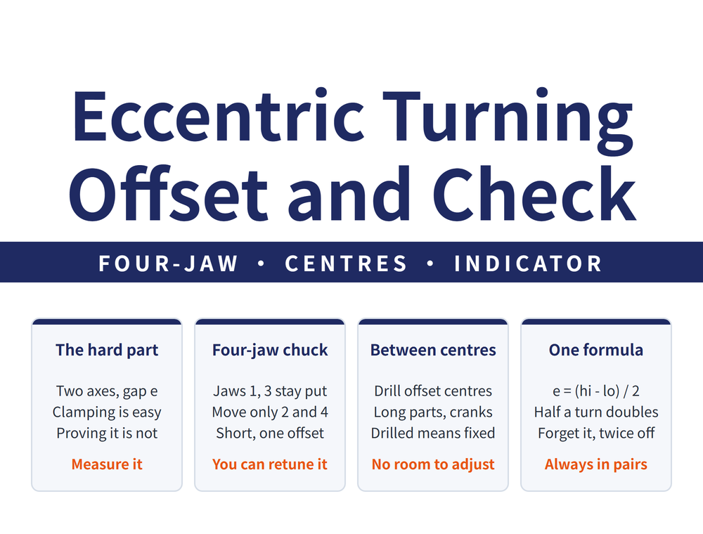
🔑 The hard part is not the cutting, it is confirming the offset is the number on the drawing. Any hold that grips will let you start cutting, but an offset that was never measured is still unknown when the part comes off. Hence two holding methods below, and three ways to check.
2. Four-jaw chuck: move only two jaws
An offset can be turned in a three-jaw or four-jaw chuck, or between centres. The four-jaw is the most direct, because each of its jaws adjusts independently.
The method: leave jaws 1 and 3 fixed and adjust only jaws 2 and 4, shifting the workpiece axis away from the chuck centre by the eccentricity e. With no offset, the four jaws sit symmetrically.
📌 Keep that split in mind — one pair fixed, one pair adjusted. When the measurement in section 6 calls for a correction, the same pair moves, so the setup converges instead of wandering.
3. Between centres: long parts and crankshafts
When the part is long and needs support at both ends, work between centres:
| Step | What is done |
|---|---|
| 1 | Find the true centre of each end face |
| 2 | Drill the offset centre holes away from those centres |
| 3 | Mount driving plate, lathe dog and tailstock live centre; the spindle axis now matches the offset axis |
| 4 | Turn the headstock end, propping the part with a screw to stop it bending |
| 5 | Reverse the part, add a soft metal protector, prop it again and turn the other end |
⚠ The offset is fixed at step 2. The centre hole positions decide everything, and nothing downstream can adjust them — the opposite of the four-jaw method, where you can measure and correct.
4. Choosing between the two
| Aspect | Four-jaw chuck | Between centres |
|---|---|---|
| Setup | Simple and quick | Needs centres found and offset holes drilled |
| Suits | Short parts, a single offset | Long parts, crankshafts offset at both ends |
| Limit | Limited grip length; long overhang is unstable | More steps |
| Can the offset be corrected | Yes, by moving the jaws | No, once the holes are drilled |
📌 In one line: short part with one offset, use the four-jaw; long part, or both ends offset, work between centres. For how the finishing pass itself should be run, see Why a Finish Turning Pass Must Run the Contour in One Go: The Continuous Cutting Principle and Two Uses for a Parting Tool.
5. The indicator check: one formula, two situations
The dial indicator is the method used most, and it rests on a single formula:
e = 1/2 × (reading at the high point − reading at the low point)
Take the indicator reading on the outside diameter at its low point and at its high point, half a turn apart, then apply the formula.
Worked example: high point 6 mm, low point 2 mm, so e = 1/2 × (6 − 2) = 2 mm.
⚠ Why the half: through half a revolution the offset section travels from its low point to its high point, so the indicator sees twice the eccentricity. Take the difference as the offset and the answer is exactly double.
6. What to do with the reading
The value of this check is that it names the jaw to move. Taking a target of e = 1 ± 0.04 mm:
| Reading | Verdict | Correction |
|---|---|---|
| e = 1/2 × (3.70 − 2) = 0.85 mm | Offset too small | Slacken jaw 4 by about 0.15 mm, tighten jaw 2 by about the same |
| Reading above the target | Offset too large | Reverse it: slacken jaw 2, tighten jaw 4 |
| e = 1/2 × (4 − 2) = 1 mm | Within tolerance | Leave it and start cutting |
📌 Corrections are always made in pairs, one slackened and one tightened, and always on the adjusting pair from section 2. Slacken without tightening, or the reverse, and the part simply moves somewhere else.
7. Off the machine: V-block and gauge blocks
Once the part is finished and being inspected on its own, the chuck is no longer the rotational datum. A V-block on a surface plate takes over.
V-block with indicator: sit the part in the vee, bring the indicator onto the high point of the outside diameter, turn the part half a revolution and read the low point. The formula is the same one. Only the datum has changed, from chuck to V-block and plate, which suits an inspection bench.
Gauge block method is static instead: sit the part in the V-block and stack gauge blocks on the far side of the offset section until they sit level with the top of the diameter, then read the stack height H2.
Y = R + H2 (R is the workpiece radius, Y the centre height of the offset section)
e = Y − X (X is the datum height from the same setup)
🔑 All three are the same idea: establish a known datum, then read how far the offset section sits from it. The indicator reads the swing between extremes; the gauge blocks measure an absolute height and subtract.
8. Frequently Asked Questions (FAQ)
Q: Why is the eccentricity formula divided by two?
Through half a revolution the offset section moves from its low point to its high point, so the indicator travels twice the eccentricity. The difference between the high and low readings is that doubled travel, and halving it gives the true offset. Skip the halving and the answer is exactly double — a figure that still looks plausible, which is why it is easy to miss.
Q: Four-jaw chuck or between centres?
It follows part length and how many offsets are needed. The four-jaw is quick, suits short parts with a single offset, and lets you correct the setting after measuring; its limit is grip length, so a long overhang becomes unstable. Between centres needs the end centres found and offset holes drilled, which is more work, but it handles long parts and lets you reverse the part for crankshafts offset at both ends.
Q: The offset is wrong. Which jaw do I move?
The adjusting pair, jaws 2 and 4; the fixed pair, jaws 1 and 3, stays put. Corrections are made in pairs: if the offset is too small, slacken one side and tighten the one opposite; if too large, reverse it. Slackening without tightening, or tightening without slackening, pushes the part to a different position and the setup starts over.
Q: Can the offset still be measured once the part is off the lathe?
Yes, by swapping the datum. Sit the part in a V-block on a surface plate, read the high point of the diameter, turn it half a revolution and read the low point, then use the same formula. The alternative is the gauge block method: stack blocks on the far side of the offset until they are level with the top of the diameter, add the stack height to the radius to get the centre height, and subtract the datum height.
When the same part also carries a knurled grip, see Knurling on a Lathe: Pattern Grades, Undersize Allowance and Spindle Settings.
For the full reading guide on this topic, see Turning: The Complete Guide.
Published: 2026-09-21 | Last updated: 2026-09-21









