
Knurling on a Lathe: Pattern Grades, Undersize Allowance and Spindle Settings
Knurling is one of the few lathe operations that forms by pressure rather than by cutting, so every setting runs opposite to the rest of the job: slow spindle, heavy feed, and a part that grows instead of shrinking. This article matches pattern grade to workpiece diameter, gives the undersize allowance, the spindle settings, and a lookup table for five knurl defects.
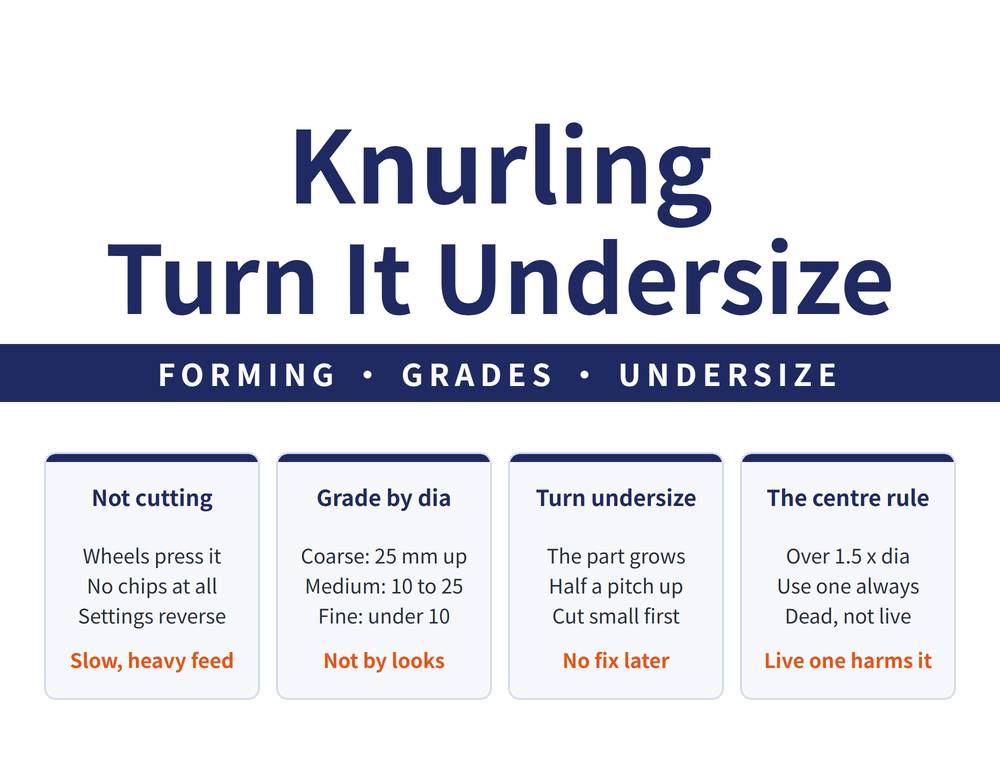
1. Knurling forms by pressure, not by cutting
Knurling presses a pattern into the surface with a hardened wheel. There is no chip.
🔑 That single fact inverts every setting: the spindle runs slow, the feed runs heavy, and the part comes out larger than it went in. Set a knurl the way you set an OD turning pass and three of the four values will be wrong.
| Purpose | Where it is used |
|---|---|
| Grip | Screws, nuts and adjusters that are turned or dismantled by hand |
| Appearance | Exposed hand-operated parts |
| Press fit | Growing the shaft diameter to create an interference or locking fit |
📌 The third one is easy to overlook: a knurl is also a way to make a shaft bigger when a press fit is needed.
2. Two patterns, and how the wheels mount
A straight knurl runs parallel to the axis. A diamond knurl is formed by two opposing helical patterns crossing each other.
| Holder type | Construction | What it can produce |
|---|---|---|
| Single wheel | One wheel pinned to the nose of the holder | Only the one pattern carried by that wheel |
| Twin wheel | Two wheels pinned face to face in a head that fits the holder | A matched crossing pattern |
A diamond pattern can be made two ways: a right-hand (R) plus a left-hand (L) wheel in a twin-wheel head, or a single diamond wheel rolled directly.
⚠ Read the wheel face when ordering or drawing stock. The face carries the brand, the material and the tooth count; a helical wheel carries the hand (R or L) on the other face. Wheels are made in high speed steel because they take heavy pressure and must resist wear; the holder is medium carbon steel.
3. Pick the grade from the diameter, not from the look
| Grade | Pitch | Teeth per inch | Workpiece diameter |
|---|---|---|---|
| Coarse | 1 mm and above | 14–20 | φ25 mm and above |
| Medium | about 0.7–1.0 mm | 22–36 | φ10–25 mm |
| Fine | about 0.4–0.6 mm | 38–48 | φ10 mm and below |
| Extra fine | 0.4 mm and below | 50–60 | Clock and watch components |
📌 The grade follows the diameter, not the preference. Put a coarse pattern on a small diameter and one tooth takes too large a share of the section, so the form has nothing to stand on.
4. Turn it undersize: the part grows about half a pitch
After knurling, the diameter grows by roughly half the tooth pitch. The blank must therefore be turned undersize against the finished dimension on the drawing.
| Pattern | Undersize allowance |
|---|---|
| Coarse | 0.8–1.0 mm and above |
| Medium | 0.4–0.6 mm |
| Fine | 0.2–0.4 mm |
🔴 Miss this step and the finished diameter is simply out of tolerance, with no way back — cutting the part down afterwards removes the pattern. For preparing the tool that takes the undersize pass, see How to Regrind a Turning Tool: Six Steps for HSS, Seven for Carbide, and the Brazed-Tool Sequence.
5. Machine settings: slow speed, heavy feed
| Item | Typical value |
|---|---|
| Surface speed | about 4.5–5 m/min |
| Spindle speed | 50–100 rpm (too fast and the pattern will not form) |
| Power feed | about 0.2–0.5 mm/rev, roughly half the pitch |
| Cleaning pass | 500–2000 rpm, flood coolant and a brass brush |
⚠ Power feed gives a more even result than hand feed. Treat the table as typical ranges and confirm against the machine and the wheel supplier catalogue.
6. The centre rule: use one, and make it a dead centre
The threshold is stated plainly: when the knurled section sits further from the chuck than 1.5 times the workpiece diameter, a centre should be used.
🔴 The stricter version is use a centre for every knurl, and make it a dead centre. The reason is not part rigidity — a live centre taking knurling pressure will damage the accuracy of the tailstock taper bore. What is lost is machine accuracy, not one part.
7. The first pass decides it: trial knurl and centre height
The result of a knurl is decided by the impression made on the first pass. Get it wrong and rolling over it again only makes it worse.
To trial: swing the holder 2–3 degrees left or right so that more than half the wheel width contacts the work, feed in about 0.2 mm or to full depth, traverse slightly, and roll about 5 mm of pattern.
📌 The trial mark also sets centre height: if the upper wheel bites deep and the lower one bites shallow, the tool centre is low, so shim it up.
For the full pass, that same 2–3 degree swing works better — lower feed resistance, and the pattern can be rolled to the end — at the cost of more burr. One or two passes is enough; more wastes time and tends to scramble the pattern. Withdraw the tool before stopping the spindle, then chamfer, deburr, wipe clean and oil.
8. Five defects and what causes them
| Defect | Causes |
|---|---|
| Pattern not sharp | Too little pressure; blunt wheel teeth; spindle too fast; poor lubrication |
| Pattern scrambled | Work, tool, post or holder not tight; too many repeat passes; spindle too fast; the two wheels have different pitches |
| Uneven depth | Tool centre off; wheels differ in sharpness; loose tool post; work unsupported or poorly supported |
| Excessive burr | Wheel face runout; traverse feed too fast; the two wheel axes are not parallel |
| Pattern distorted | Work diameter does not suit the wheel pitch; wheel axes not parallel; traverse feed too fast or too slow |
📌 Non-parallel wheel axes appears in both the burr row and the distortion row, so check it first when a twin-wheel head shows either. When the same part also carries shoulders, see Shoulder Turning: Corner Types, the Reversed Rough and Finish Sequence, and Finish Allowance.
9. Frequently Asked Questions (FAQ)
Q: Why does knurling run at only 50–100 rpm?
Because knurling is not cutting. The wheel displaces material into a pattern, and the material needs time to flow into place. Run too fast and the wheel cannot press the form to full depth, so the pattern comes out blurred. Spindle speed is one of four causes of a dull pattern; the others are insufficient pressure, blunt wheel teeth and poor lubrication.
Q: How much undersize should the blank be?
The diameter grows by roughly half the tooth pitch, so the allowance follows the pattern: 0.8–1.0 mm or more for coarse, 0.4–0.6 mm for medium, 0.2–0.4 mm for fine. There is no recovery from getting this wrong, because turning the part down afterwards removes the pattern along with the material.
Q: Is a centre always needed, and can it be a live centre?
A centre should be used once the knurled section is more than 1.5 times the workpiece diameter from the chuck, and the practical advice is to use one every time, as a dead centre. The reason is not part rigidity: knurling pressure carried through a live centre damages the accuracy of the tailstock taper bore, and that loss follows every part cut afterwards.
Q: The pattern came out crooked. Can another pass fix it?
Usually not. One or two passes is the working limit, and too many repeat passes is itself a listed cause of a scrambled pattern. A crooked result normally traces back to centre height or clamping rigidity on the first pass, so rolling again just stacks a second layer on a bad base. Check centre height and the tightness of the post and holder, then trial 5 mm again before running the full length.
When the same part also needs an eccentric feature, see Eccentric Turning: Two Workholding Methods and Three Ways to Check the Offset.
For the full reading guide on this topic, see Turning: The Complete Guide.
Published: 2026-09-21 | Last updated: 2026-09-21









