
Hydraulic Workholding Basics: Pascal's Principle, System Layout, Air vs Hydraulic
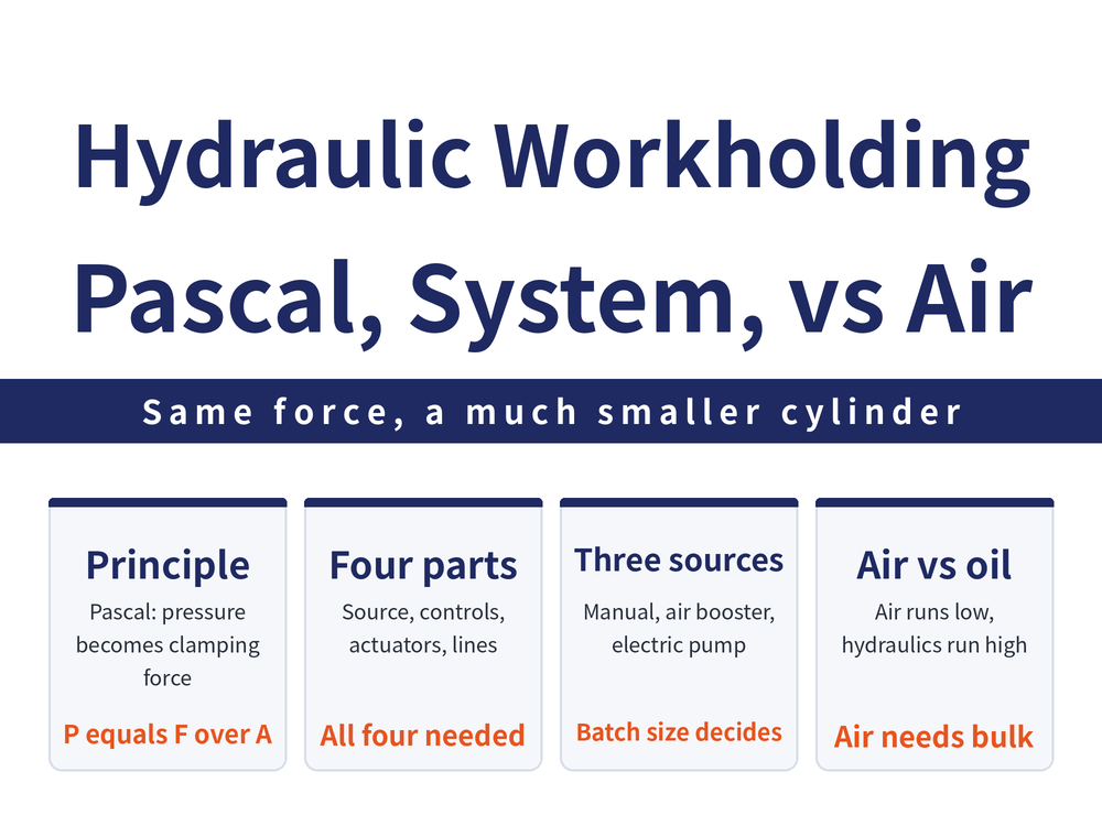
A hydraulic fixture holds the workpiece with pressures tens of times higher than shop air, so the elements stay far smaller for the same clamping force. This guide starts from Pascal's principle and the basic equation, then walks through the four parts of a hydraulic system, the three power sources, what makes a fixture cylinder different, and how air and hydraulics compare — and it closes on the point that confuses people most: the hydraulics here hold the part, not the tool.
1. What Hydraulic Workholding Is: Pascal's Principle Applied
Hydraulic workholding uses a hydraulic cylinder to convert hydraulic pressure into clamping force that holds the workpiece. It is an application of hydrostatics, and the principle comes from Pascal's principle (pressure in a confined fluid acts equally throughout), stated by Blaise Pascal (1623-1662).
The basic equation is one line: pressure equals force divided by the area it acts on.
P = F / A F: force (N) | P: pressure (bar) | A: acting area (cm²). Conversions: 1 kgf = 9.8 N; 1 bar = 10 N/cm² ≈ 1.02 kgf/cm².
This article's worked example is a 16 mm bore cylinder at 500 bar:
F = P × A = 500 × (1.6² × 3.14 / 4) = 1,004.8 kgf (bore entered in cm, i.e. 1.6 cm)
That example feeds the bar figure of 500 straight into the arithmetic, without applying the 1 bar ≈ 1.02 kgf/cm² conversion. This article reproduces that arithmetic as it stands, without correcting it. For real selection, use the supplier's thrust table. For how large the clamping force should be in the first place, see How Much Clamping Force Do You Need: Cutting Force, Bolt Force and Two Worked Examples.
2. The Four Parts of a Hydraulic System
Whatever the size of the fixture, a hydraulic system is built from these four blocks:
| Block | What it covers |
|---|---|
| Pressure source | The hydraulic power unit |
| Control elements | Directional valves, pressure-regulating valves, sequence valves and so on |
| Power transmission elements | Hydraulic and pneumatic clamping cylinders |
| Piping, fittings and monitoring devices | Steel tube, hose, fittings and pressure switches |
The control elements a fixture system commonly uses are directional control valves, relief valves, reducing valves, sequence valves, check valves and pilot-operated check valves, plus pressure switches with an electrical or hydraulic signal output. For the design sequence of the fixture itself, see What Is a Jig and Fixture.
3. Choosing the Power Source: Three Pumps
The basic source of hydraulic pressure is the hydraulic pump, the device that turns mechanical power into fluid pressure. Fixture systems use fewer pump types than general hydraulics — three, chosen by batch size:
| Type | Where it fits | Notes |
|---|---|---|
| Manual pump | Small batches, fixture installation and testing | Piston type, for infrequent operation; can be paired with pressure adjustment and a pressure switch for safer operation |
| Air-driven intensifier | Hydraulic fixtures at small to medium flow | Takes existing shop air as input and multiplies it into hydraulic pressure through the piston area difference |
| Electric pump | Medium to large batch production fixtures | Electric-motor-driven hydraulic power unit |
Intensifier relation: P1 × A1 = P2 × A2, output P2 = P1 × (A1/A2), intensification ratio = A1/A2. A1 and A2 are the acting areas of the pistons on the two sides; P1 is the air pressure in, P2 the hydraulic pressure out.
Electric-motor-driven power units split into two construction classes: piston type, which is high pressure and runs in either direction of motor rotation, and gear or vane types, which are low to medium pressure.
4. A Fixture Cylinder Is Not a General-Purpose Cylinder
Cylinders in a fixture system have a shorter stroke than general hydraulic and pneumatic cylinders, and internal leakage needs closer attention in the design. By oil feed they split into two:
| Type | Ports | Return stroke and fit |
|---|---|---|
| Single-acting cylinder | Inlet port only | Returns by spring or another external force pushing the piston back |
| Double-acting cylinder | One extra return-side port | Return time is controllable; suits large fixtures and automated load/unload |
Cylinders developed specifically for fixtures from the 1950s onward share three traits: a stroke kept short to suit fixture needs; a piston speed of 0.01–0.25 m/sec., slower than general hydraulic cylinders; and leakage behaviour of slight leakage while moving and zero leakage at rest. These are general figures — take individual models from the supplier's specification.
5. Air or Hydraulic: The Basic Comparison
| Item | Pneumatic | Hydraulic |
|---|---|---|
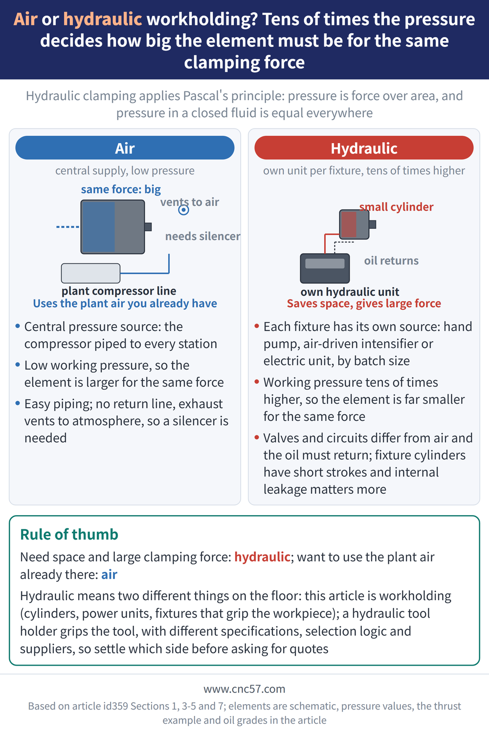
| Pressure source | Usually central supply: a plant compressor piped to each workstation | Each fixture has its own power unit |
| Working pressure | Normally up to 7 bar (about 7 kgf/cm²) | Up to 500 bar, or higher |
| Element size | Air cylinder is bulkier for the same clamping force | Hydraulic cylinder is smaller for the same force |
| Piping and control | Piping is easier at only 5-7 bar; there is no return line, exhaust air vents to atmosphere, so silencers are used | Valves and circuit design differ from air; the oil must return |
Put another way, the tenfold-plus pressure gap decides how big the elements have to be for a given clamping force. Go hydraulic when space is tight or the force is high; stay pneumatic when you can reuse existing shop air and want the lower cost. For the pneumatic force calculation, see How to Calculate Pneumatic Clamping Force.
6. Oil and Temperature: Direction First, Specification Second
Ambient temperature and hydraulic operating temperature both run -10°C to +50°C, and hydraulic oil is specified to DIN 51524. It is grouped into three grades by oil temperature:
| Oil temperature (°C) | Grade (DIN 51524) | Example use |
|---|---|---|
| 10–40 | HLP22 | Poppet-type directional valves, hydraulic fixtures |
| 15–50 | HLP32 | General machine tools |
| 20–60 | HLP46 | Construction machinery |
Read the table for direction rather than for numbers: the hotter the oil, the higher the grade, with hydraulic fixtures in the lowest grade.
For the actual brand and change interval, follow the oil supplier's specification or the text of DIN 51524, and do not use this table as a purchasing specification.
7. This Is the Work Side, Not the Tool Side
"Hydraulic" points at two entirely different things on the shop floor, and that is the easiest confusion in this topic.
This article is about work holding: hydraulic cylinders, power units and hydraulic fixtures that grip the part being machined. Tool holding is about how a holder grips the cutting tool, and the hydraulic tool holder also uses fluid pressure but grips the tool, with different specifications, selection logic and suppliers. Settle which side you need before requesting a quote.
Frequently Asked Questions (FAQ)
Q: What is the main difference between hydraulic and pneumatic fixtures?
Pressure level. Air is normally used up to 7 bar while hydraulics run to 500 bar or higher, so for the same clamping force an air cylinder has to be larger than a hydraulic one. Air wins where the plant already has central compressed air and easy piping.
Q: For small batches or a first trial, do I need an electric power unit?
No. A manual pump is exactly what small-batch work and fixture installation or testing call for, and it can be paired with pressure adjustment and a pressure switch for safety. Small to medium flow can use an air-driven intensifier; electric pumps are for medium to large batches.
Q: Which oil should a hydraulic fixture use?
Hydraulic oil is specified to DIN 51524 and graded by oil temperature: the hotter the oil, the higher the grade, with hydraulic fixtures in the lowest grade. This article states no viscosity figures or change conditions, so take the brand and interval from the oil supplier's specification or the standard itself.
Q: Are hydraulic fixtures and hydraulic tool holders the same thing?
No. A hydraulic fixture holds the workpiece and belongs to work holding; a hydraulic tool holder grips the cutting tool and belongs to tool holding. Both use fluid pressure to generate clamping force, but the specifications, selection logic and suppliers are entirely different, so separate them before searching or requesting a quote.
This article is part of Workholding and Fixtures: The Complete Guide - Locate First, Then Clamp; How Much Force and Where It Comes From; that guide shows how the whole topic fits together.
Published: 2026-08-28 | Last updated: 2026-10-21









