
Workholding and Fixtures: The Complete Guide - Locate First, Then Clamp; How Much Force and Where It Comes From
A badly held workpiece cannot be saved by any machine or cutter. But "badly held" covers two things that get mixed up: the position was never fixed, and the force was wrong. This guide follows the order the decisions are actually made in - locate first, then work out the clamping force, then choose where the power comes from, then the lathe side, changeover and multi-face work, and only at the end the design workflow itself. Every section points to an article you can read next.
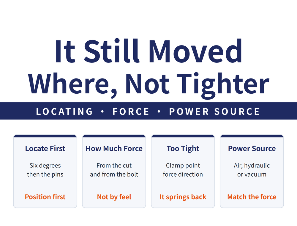
1. First, What a Fixture Is Solving
A jig or fixture locates and clamps a workpiece on the machine. A jig differs from a fixture in one function only - whether it guides the tool. The first article of the line covers those definitions and the classifications.
| Article | When to read it |
|---|---|
| What Is a Jig and Fixture | The entry point for the line. Locating, clamping and guiding, plus three axes of classification |
| Workholding and Fixture Basics | Enough on its own if you only want the general idea and are not designing a fixture |
The difference between the two is whether you are about to design something: the first covers definitions and classification, the foundation for anyone going on to design a fixture; the second runs straight from six degrees of freedom and the 3-2-1 location principle to vise, magnetic and vacuum-chuck practice - a complete picture for anyone who just needs the part held and is not designing anything. The drawing symbols are in the first article - a fixture drawing is not an ordinary part drawing, and without those marks the figures in the later articles are hard going.
2. Locate First, Then Clamp - The Order Matters
When a part goes onto a fixture, the first decision is not how tightly to hold it, but the one position it is allowed to sit in. Locating deals with restraining six degrees of freedom; clamping only holds that position down.
| Article | When to read it |
|---|---|
| How a Workpiece Is Located | One article, but it is the foundation of the line. |
The diamond pin section is worth the read on its own: two round pins can stack up enough tolerance that the part will not go on, and narrowing the second one is the fix, not a saving. That pattern - not too loose, but too exact and therefore jammed - runs through fixture design.
3. How Much Clamping Force: Calculated, Not Felt
This section holds two opposite failures: too little and the part moves, too much and it distorts. Read both, or you will adjust in the wrong direction.
| Article | When to read it |
|---|---|
| How Much Clamping Force Do You Need | Read this first. The demand side worked back from cutting force, the supply side from the bolt |
| Why Vise Clamping Distorts the Workpiece | When a part measures well in the vise and moves once released |
The second one overturns a natural assumption: movement after release usually means it was held too tightly or in the wrong place, or that the force direction made the clamping force double. So when that symptom appears, do not reach for more force first.
4. Where the Power Comes From: Air, Hydraulic, Vacuum
Once the required force is known, next comes what actually supplies it. The three sources cover quite different ground; it is not a question of which is better.
| Article | When to read it |
|---|---|
| Pneumatic Clamping Math | When sizing an air cylinder. The formula is one line; the units catch people |
| Hydraulic Workholding Basics | When air cannot supply the force, or the components take too much room |
| Hydraulic Fixture Valves and Plumbing | Once hydraulic is chosen and the system has to be built |
| How Hard Does a Vacuum Chuck Hold | For thin plate, easily distorted parts, or work with no side to grip |
The division is clear: air is cheap, fast and limited in force; hydraulic gives much more force from smaller components but needs a system built around it; vacuum grips no edge at all and lets atmospheric pressure hold the part down. Read the hydraulic pair in order - basics first, then valves and plumbing once you have committed, because the second decides whether the system overheats and whether it can run unattended. Note that the hydraulics here hold the workpiece, which is not the same as a hydraulic toolholder gripping a cutter.
5. The Lathe Side: Chucks and Jaws
Most of the above is work on a mill table. A lathe is a different problem: the workpiece is turning, so holding it also has to control concentricity.
| Article | When to read it |
|---|---|
| How to Use a Lathe Chuck | When concentricity will not come right, or you are unsure whether to bore soft jaws |
Its most direct statement: the same bar held in hard jaws and in soft jaws does not run equally true. Soft jaws have to be bored in place, which is why they are more trouble and more accurate. How much gripping force to set is covered at the end of the article.
6. Changeover Time and Faces per Setup
The earlier sections are about holding the part securely and accurately. This one is about two efficiency problems around the holding: downtime at changeover, and how many faces one setup can finish.
| Article | When to read it |
|---|---|
| Zero-Point Clamping Systems | When every fixture change means re-centring and the machine sits idle |
| Self-Centring and Indexing-Table Fixtures | When the part will not centre on the fixture, or one component needs turning over three times |
They cure different pains: zero-point clamping saves the time between batches; self-centring and indexing save re-fixturing the same part. One less turnover is not only time saved, it is also one less chance to locate it slightly differently. The zero-point article closes by distinguishing itself from quick-change toolholding - the two are easily confused.
7. Designing One Yourself: How the Workflow Runs
The first six sections are knowledge of the pieces. When it comes to designing, the hard part is not the drawing, it is asking the right questions before you start.
| Article | When to read it |
|---|---|
| How to Run a Fixture Design Workflow | Read it before opening a project. Five steps and a four-part data collection checklist |
That cost section is worth handing to purchasing on its own: tighter is not better on a fixture, it converts directly into money. For how to read the accuracy the part itself demands, start with Reading Tolerance and Fit; for which face the first cut sits on, see Choosing a Locating Datum. What the fixture has to hold is decided by those two.
8. Frequently Asked Questions (FAQ)
Q: Where should I start in these 13 articles?
It depends what you are doing. To hold the part in front of you properly and you are not designing anything, the second article in section 1 - Workholding and Fixture Basics - is enough on its own. To choose an off-the-shelf fixture, go straight to section 4 for the power source, or section 5 if it is a lathe. To design one yourself, read the design workflow in section 7 first - it tells you what to gather before drawing anything - then come back to the earlier sections as needed.
Q: The part distorts once I release it. Is the clamping force too low?
Usually the opposite. Distortion on release means the part was deformed while clamped, machined in that deformed shape, and sprang back when the force came off. What to examine is where the clamps sit, whether the force direction is right, and whether force is being applied over a thin wall or an unsupported area - not how hard it is being squeezed. The vise article in section 3 separates the three causes. If you genuinely need to confirm the force is sufficient, work it back from the cutting force using the first article in that section rather than judging by feel.
Q: Air, hydraulic or vacuum - which suits a small shop?
Work out the force you need first and the answer usually follows. Air has the lowest cost and maintenance burden and most shops already have compressed air, so within its force range it is the least trouble. Go hydraulic when the required force is beyond what air can give or the components will not fit, but remember hydraulic means building a system, and the valves and plumbing decide how maintainable it is. Vacuum is a special case: it does not solve a force problem but a shape one - thin plate and parts with no side to grip. They are not tiers of quality, they cover different ground.
Q: What Is a Jig and Fixture vs. Workholding and Fixture Basics - which one should I read?
Both are entry points; the difference is whether you are about to design something. What Is a Jig and Fixture covers definitions, classification and how to read the drawing symbols - the foundation for going on to the rest of the line, or designing one yourself. Workholding and Fixture Basics runs straight from six degrees of freedom and the 3-2-1 location principle to vise, magnetic and vacuum-chuck practice in one article - the complete basic picture for anyone who just needs the part held and is not getting into design detail. The two are not in conflict; anyone designing a fixture will usually use both, just in a different order.
Published: 2026-09-09 | Last updated: 2026-09-10









