
Grinding a Stepped Shaft: Reversal Position, Wheel Backoff and Radiused Corners
A plain shaft is easy to grind. Add a shoulder and three things get harder at once: the wheel has to reverse close to the shoulder without touching it, the corner must not round over, and the wheel face takes heavy side pressure. This article covers reversal setting, where infeed is allowed, and the two corner geometries.
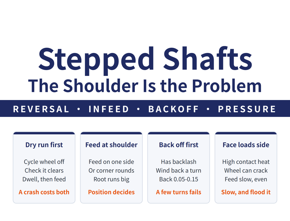
1. The shoulder is where the difficulty is
On a plain shaft the wheel simply traverses. Add a shoulder and three things get harder at once:
| Difficulty | What goes wrong |
|---|---|
| Reversal position | The wheel must come as close as possible without touching — a crash takes wheel and part together |
| Corner rounding | The cylinder near the shoulder root ends up larger in diameter than the rest |
| Side pressure on the face | The wheel takes heavy side load and can shatter if handled badly |
🔑 All three happen at the same place — the shoulder. This article is about the few millimetres next to it. For the same geometry made on a lathe, see Shoulder Turning: Corner Types, the Reversed Rough and Finish Sequence, and Finish Allowance.
2. The diameter beside the shoulder: length against wheel width
There is a single criterion for traverse or plunge: the length to be ground against the width of the wheel.
| Condition | Method |
|---|---|
| Ground length shorter than the wheel width | Usually plunge grinding |
| Surface much longer | Traverse grinding |
📌 Roughing has a third option. Where the diameter next to the shoulder is not held tightly, plunge grind that section to size first and traverse grind the rest. It is easier to set, and it deals with the hardest section first.
3. Four points on traverse grinding, all about the reversal
| # | Practice |
|---|---|
| 1 | Cycle the reversal several times with the wheel stopped to confirm it clears the shoulder face by as little as possible |
| 2 | At the shoulder end of the stroke, let the table dwell briefly so the surface next to the shoulder is properly ground |
| 3 | Infeed only at the reversal on the shoulder side |
| 4 | Where accuracy allows, plunge the section beside the shoulder first, then traverse the rest (section 2) |
🔴 Point 3 is the one most often missed, and its symptom hides well. Feeding in at the other end rounds the corner over, and the result is a cylinder at the shoulder root larger in diameter than the rest of the journal — the middle measures correctly while the section next to the shoulder runs oversize, and that is usually the fitting surface.
⚠ Point 1 is a dry run: cycle the reversal with the wheel stopped. It takes under a minute and saves a broken wheel and a scrapped part.
4. Two geometries at the corner
Shoulder faces on shafts and sleeves are usually ground with the wheel face during the diameter operation. How it runs depends on the form where the face meets the diameter:
| Corner form | Method |
|---|---|
| Undercut groove | Grind the diameter, then hand traverse the table and grind with the wheel face |
| Radiused | Dress the wheel corner to the radius first, then sequence by the length of the diameter |
| Neither | Same as radiused, but with the highest risk of shattering the wheel (section 7) |
📌 The wheel face is usually dressed to about 1 degree, which reduces the contact area with the work, avoids burning and improves the finish.
5. Undercut groove: back the wheel off first
This is the step most often done wrong. After the diameter is ground and before the face is ground, the wheel must be backed off a little.
🔴 Winding the handwheel back a few divisions does not do it. There is backlash between the leadscrew and the nut, and a few divisions only takes up that backlash — the wheel has not moved. Instead, wind back a full turn, then wind in again to a point a few divisions short of the original setting.
The backoff is generally 0.05–0.15 mm. Too much and a raised step is left at the root of the shoulder face.
⚠ Why it matters: grinding the face deflects the wheel under axial load, and without the backoff that deflection grinds the diameter undersize — the diameter just finished loses size, right where the shoulder is.
📌 In volume production of shouldered shafts and sleeves there is another route: a specially dressed wheel is run with the wheel axis at a fixed angle to the work axis, feeding in at an angle so that diameter and face are ground together, which raises output.
6. Radiused corner: two lengths, two sequences
First dress the wheel corner to the radius: a hand-held diamond will do where the radius is not critical, and a dedicated radius dressing attachment where it is.
| Length beside the shoulder | When the diameter reaches size |
|---|---|
| Short | Stock left on, finished after the face |
| Long | Diameter to size first, face handled separately |
Short diameter sequence: plunge grind the diameter leaving 0.03–0.05 mm of stock; back the wheel off (the distance follows the shoulder height); hand traverse the table and feed the face in until all the stock is removed; wind the wheel in slowly to bring the diameter to size; finally traverse the table and withdraw the wheel.
Long diameter sequence: traverse grind the diameter to size first, then grind the face as above. When the wheel has fed in to within 0.02–0.05 mm of the ground diameter, withdraw the table longitudinally first and only then back the wheel off.
🔑 The two differ in when the diameter reaches final size, and the retract order reverses with it: the short case finishes the diameter last, while the long case pulls the table before the wheel.
7. Neither groove nor radius: the wheel can shatter
A shoulder face with no undercut groove and no corner radius is ground the same way as a radiused one, but the risk is not the same.
🔴 Grinding this kind of face puts heavy side pressure on the wheel, and careless handling can shatter it. There are only two countermeasures: move the table carefully, and keep the feed small and even so the wheel is never overloaded.
⚠ Heat is the other issue: face grinding gives a large contact area and high temperature, so ample coolant is needed or the surface will burn.
📌 For the underlying workholding, motions and grinding data, see Cylindrical, Internal and Surface Grinding: Workholding, Motions and Grinding Data.
8. Frequently Asked Questions (FAQ)
Q: The diameter measures oversize near the shoulder. Why?
Usually the infeed is being taken at the wrong end. When traverse grinding a stepped shaft, infeed is only allowed at the reversal on the shoulder side. Feeding in at the other end rounds the corner over, and the cylinder at the shoulder root ends up larger in diameter than the rest. The symptom hides well because the middle of the journal measures correctly, and the oversize section next to the shoulder is usually the fitting surface.
Q: Why back the wheel off before grinding the face, and by how much?
Because grinding the face deflects the wheel under axial load, and without a backoff that deflection grinds the freshly finished diameter undersize. The backoff is generally 0.05 to 0.15 mm; too much leaves a raised step at the root of the shoulder face. How it is done matters: leadscrew and nut have backlash, so winding back a few divisions only takes up that backlash. Wind back a full turn, then wind in to a few divisions short of the original setting.
Q: How should the reversal position be set safely?
Dry run it. With the wheel stopped, let the table cycle through its reversal several times and check that the wheel clears the shoulder face by as little as possible without touching, then start the wheel. Also let the table dwell briefly at the shoulder end of the stroke, or the surface next to the shoulder will not be properly ground. The check takes under a minute and saves a broken wheel plus a scrapped part.
Q: The wheel shattered while grinding a shoulder face. Was it a bad wheel?
Look at the handling first. Grinding a shoulder face puts heavy side pressure on the wheel, particularly on a shaft with neither an undercut groove nor a corner radius, and careless handling will break it. The countermeasures are to move the table carefully and keep the feed small and even so the wheel is not overloaded. Face grinding also has a large contact area and runs hot, so ample coolant is needed or the surface will burn.
This article is part of Grinding Wheels and Machines: The Complete Guide - Reading the Wheel, Mounting It, Dressing It, and Tracing Defects; that guide shows how the whole topic fits together.
Published: 2026-09-21 | Last updated: 2026-10-24









