
Turning Tool Holder Guide: ISO Codes & Clamping
External turning tool holder codes combine insert shape, lead angle, clamping system, shank size and cutting direction into a standardized system, letting users quickly select the right tool for outer-diameter turning. Understanding the code rules and clamping differences improves machining stability, chip control and tool life in CNC turning.
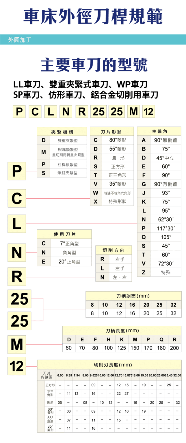
1. Holder Code Structure
A typical code (e.g. PCLNR2525M12) is built from several fields covering clamping system, insert shape, lead angle, cutting direction and dimensions. Reading each field lets you quickly identify the tool spec and speed up selection.
| Field | Meaning |
|---|---|
| Clamping code | Insert clamping method |
| Insert shape | Insert geometry code |
| Lead angle | Tool entering angle |
| Cutting direction | Right / left / neutral |
| Shank size | Shank width × height |
| Insert size | Insert edge-length spec |
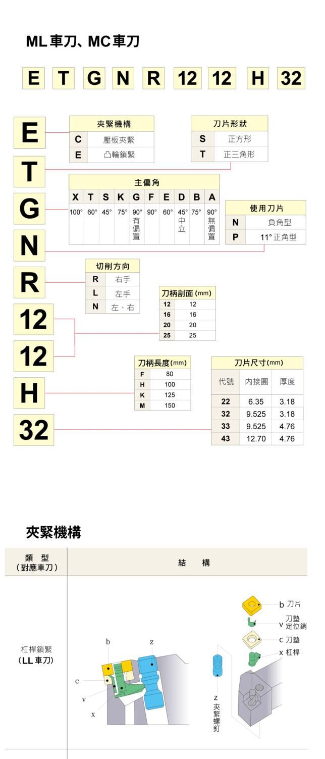
An OD turning tool is only one kind; for facing, parting, threading and boring tools and which surface each cuts, see Types of Turning Tools.
2. Insert Shapes and Applications
Insert shape drives edge strength and available cutting space. Roughing generally favors stronger shapes with larger nose angles (C, S); finishing favors smaller nose angles for contouring and clearance (V, D).
| Code | Shape | Suggested use |
|---|---|---|
| C | 80° rhombic | Roughing, general |
| S | Square | Roughing, strong edge |
| D | 55° rhombic | Finishing |
| V | 35° rhombic | Finishing, clearance |
| T | Triangular | General |
| R | Round | Profiling, radius work |
3. Lead Angle and Cutting Behavior
Lead angle affects cutting force direction, chip evacuation and surface quality. Common values are 90°, 95°, 75°, 45° and 117.5°. As a rule, roughing tends toward larger lead angles to carry the load, while finishing tends toward smaller angles for a better finish.
| Item | Content |
|---|---|
| Common lead angles | 90° / 95° / 75° / 45° / 117.5° |
| Affects | Force direction, chip control, surface quality |
| Guideline | Roughing → larger; finishing → smaller |
4. Shank Size and Rigidity
Shank cross-section directly affects rigidity and vibration resistance — the larger the size, the higher the rigidity. Common sizes are 8×8, 10×10, 12×12, 16×16, 20×20, 25×25 and 32×32 (mm). Where machine and holder space allow, choose a larger shank for stability.
| Item | Content |
|---|---|
| Common shank sizes (mm) | 8×8 / 10×10 / 12×12 / 16×16 / 20×20 / 25×25 / 32×32 |
| Affects | Tool rigidity, vibration resistance |
| Principle | Larger size → higher stability |
5. Cutting Direction (Hand)
Cutting direction is coded as R (right-hand), L (left-hand) or N (neutral). It sets the feed direction and tool path, and must match the workpiece machining direction and machine layout during selection.
6. Clamping Systems and Their Effect
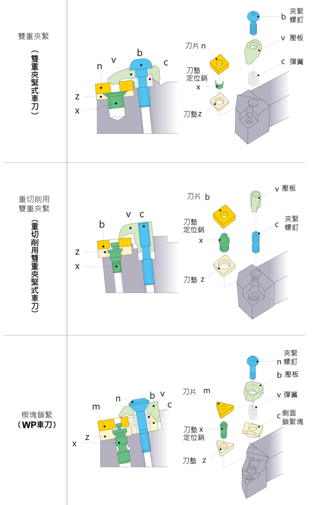
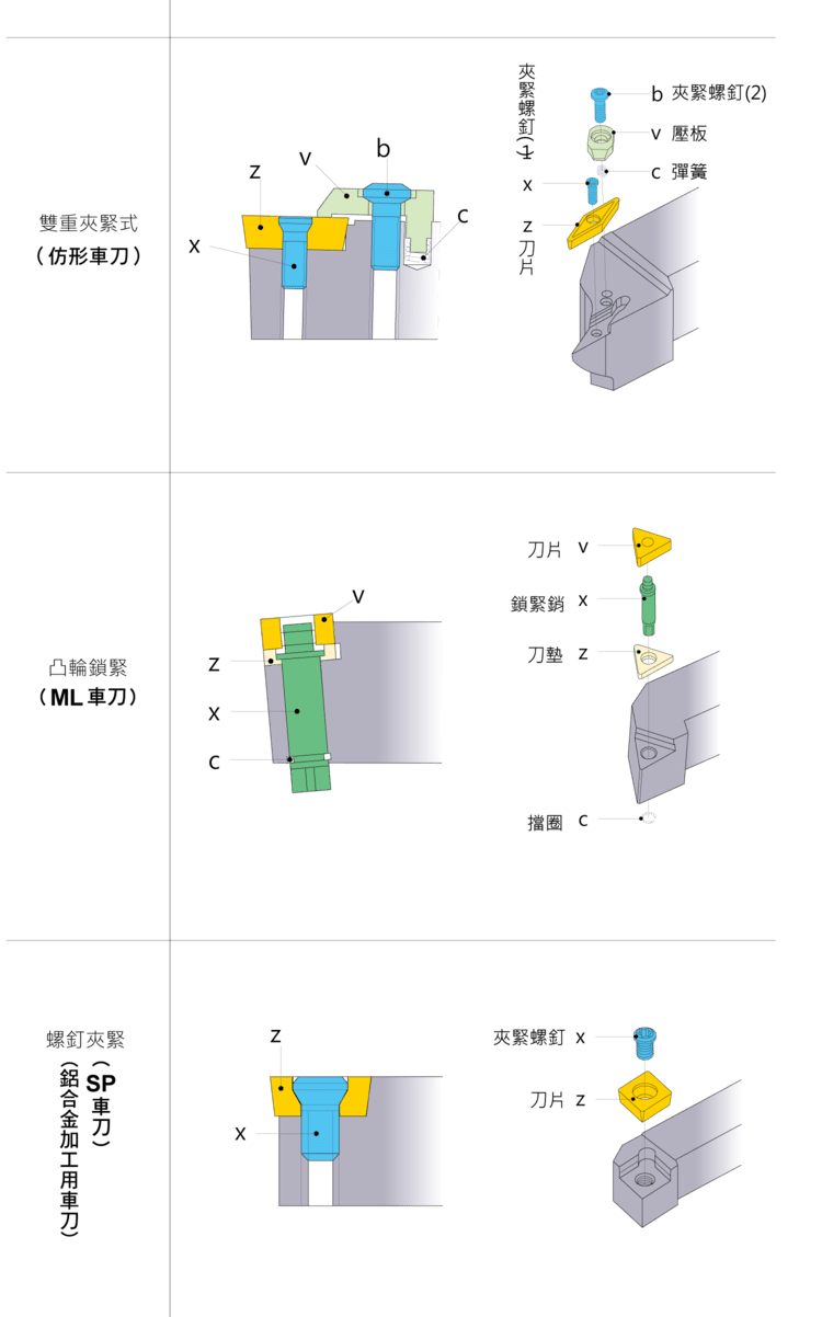
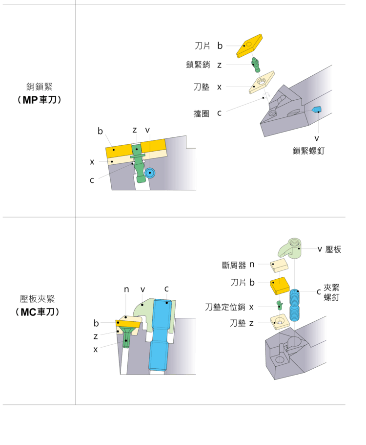
The clamping system affects insert seating accuracy, stability and vibration resistance, which show up directly in machining quality and change-over efficiency. Common systems and their uses:
| Clamping | Trait | Best for |
|---|---|---|
| Double clamp | High stability | Heavy cutting |
| Lever lock | Fast change | General work |
| Screw clamp | Simple structure | Light cutting |
| Top clamp | High-accuracy seating | Finishing |
| Cam lock | Quick change | Volume production |
7. Tool Types and ISO Selection
By rigidity, versatility and operation type, common external turning tools are listed below. In practice, roughing favors larger shanks and strong clamping; finishing pairs small inserts with high-accuracy seating; high throughput uses quick-change systems and stable chip control.
| Type | Trait |
|---|---|
| LL holder | High rigidity |
| SP holder | General purpose |
| WP holder | Heavy cutting |
| MC holder | Aluminum |
| ML holder | Finishing |
8. Keys to Optimizing External Turning
The core factors in external turning are shank rigidity, insert shape and clamping stability. Balanced together, they raise machining quality, cut vibration and extend tool life. Calculate actual speed and feed from your material and machine — see the Turning Machining Formulas; for rake/clearance pairing see the Turning Tool Rake & Clearance Guide.
FAQ
Q: How do I read a code like PCLNR2525M12?
An external turning holder code is built from fields for clamping method, insert shape, lead angle, cutting direction, shank size and insert size. Read field by field to identify the spec. Exact field definitions follow each brand's own catalog.
Q: Which insert shape for roughing vs finishing?
Roughing favors stronger shapes such as C (80° rhombic) and S (square); finishing favors smaller nose angles for clearance and contour, such as V (35°) and D (55°).
Q: Is a bigger shank always better?
A larger shank gives higher rigidity and vibration resistance and more stable cutting. It still has to fit the machine's tool pocket and the working space, so choose the largest shank the setup allows.
Q: How do I choose a clamping system?
Heavy cutting uses double clamp for stability; finishing uses top clamp for accurate seating; for change-over speed and volume work, use lever or cam quick-clamp systems. Choose by operation type and stability need.
For the full reading guide on this topic, see Turning: The Complete Guide.
Published: 2026-03-25 | Last updated: 2026-10-20









