
Why Vise Clamping Distorts the Workpiece: Clamp Point, Structure, Force Direction
A part sits square in the vise, machines fine, and measures out of spec once released. This is one of the questions shops ask most. The cause is usually not too little clamping force but too much, applied at the wrong point, or in a direction that forces the clamp to work twice as hard. This guide separates the three causes — clamp point, vise structure, force direction — then compares four ways to hold the part.
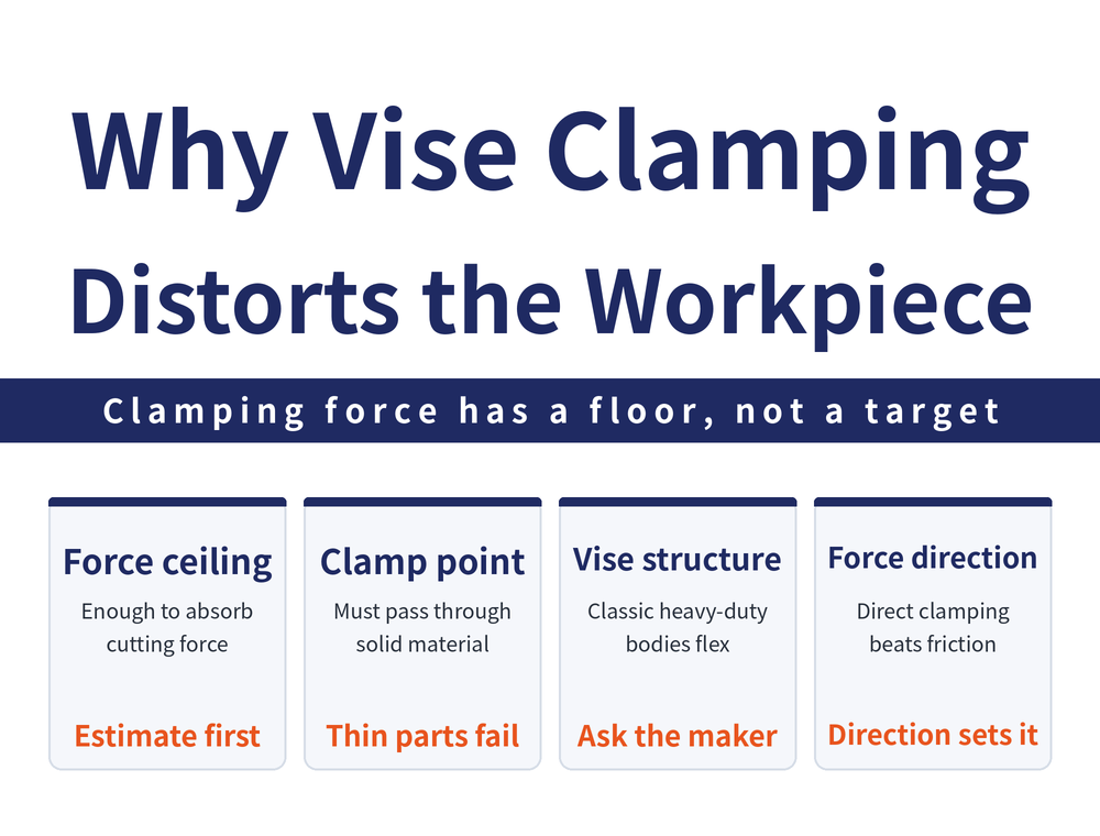
1. Turn the Question Around: More Clamping Force Is Not Better
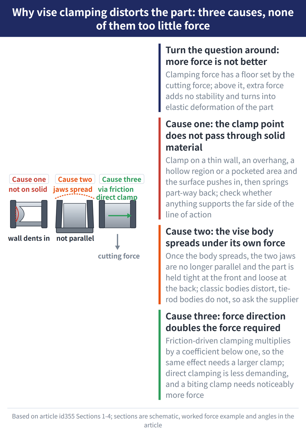
The first instinct when a part distorts is to check whether it was clamped tightly enough. But clamping force has one defined job: hold the part securely, with a magnitude at least large enough to absorb the cutting force the machine applies to it. That gives clamping force a floor set by the cutting force. Above that floor, extra force does not make the cut more stable — it turns into elastic deformation of the part.
So fixture design runs in this order: estimate the cutting force, then work back to the clamping force needed. In principle the clamping force must generate enough friction to resist the cutting force, and the cutting force itself can be derived from cutting power, drive efficiency and cutting speed. That relationship defines a minimum, not a target. A part that only goes out of spec after release has almost always been clamped far above that minimum, or clamped in the wrong place. How to calculate that minimum, and which quantities go into it, is covered in How Much Clamping Force Do You Need: Cutting Force, Bolt Force and Two Worked Examples.
2. First Cause: The Clamp Point Does Not Pass Through Solid Material
The most basic rule for manual workholding is one sentence: the clamp point must pass through solid material in the part. Clamp on a thin wall, an overhanging section, a hollow region of a casting or an area that has already been pocketed out, and the same force pushes the local surface in. It springs part of the way back on release, and the measurement no longer matches.
Thin parts and box-shaped parts break this rule most often, because the outside offers a large flat face to clamp on and there is not always material behind it. The check is direct: follow the line of action of the clamping force and see whether anything supports the far side. If nothing does, move the clamp or add a support element behind the face first.
3. Second Cause: Whether the Vise Body Itself Flexes
Vises are not one thing. The two common classes behave very differently:
| Type | Clamping principle | Body distorts when clamped |
|---|---|---|
| Free vise | Mounts in the machine T-slot; an inclined face gives both downward and forward clamping force | |
| Heavy-duty mechanical vise (classic body) | Mechanical force multiplication, high clamping force | Yes |
| Heavy-duty mechanical vise (tie-rod design) | Mechanical force multiplication with a patented tie-rod structure | No |
A free vise clamps through an inclined face, so besides pulling the part forward it also presses it down. That is how it seats the part against the vise bed, but it also means part of the clamping force acts downward. A heavy-duty mechanical vise delivers far more force, and whether its own body is spread open by that force depends on the structure — classic bodies distort when clamped, bodies using the patented tie-rod design do not.
This is worth confirming on its own, because once the body spreads, the two jaws are no longer parallel: the part gets clamped tight at one end and loose at the other, and springs back on release. When buying, ask the vise supplier directly for the body type and the jaw parallelism specification under clamping load.
4. Third Cause: Force Direction Doubles the Force Required
For the same part, applying force in different directions changes how much clamping force you need. There are two paths. In direct clamping, the clamping force opposes the cutting force directly. In friction-driven clamping, the clamping force first becomes friction, and the friction resists the cutting force. The second path multiplies by a friction coefficient below 1, so the same effect needs a larger clamp. In short, clamping in a direction that acts directly is less demanding than relying on friction.
The contact condition at the clamp point changes the requirement too: a clamp point that bites into the part adds the friction angle a second time, so a biting clamp needs noticeably more force, and more force brings back the problem in section 1. The two worked examples, with their premises, angles and figures, are in How Much Clamping Force Do You Need: Cutting Force, Bolt Force and Two Worked Examples.
5. The Friction Coefficient Is Not a Constant
The friction coefficient is not fixed either: wet cutting runs lower than dry because cutting fluid gets between the surfaces, and cast iron on cast iron sits above steel on steel, so do not build a safety factor on a single figure. The direction of each effect and how to obtain actual values are set out in How Much Clamping Force Do You Need: Cutting Force, Bolt Force and Two Worked Examples.
6. Would a Different Holding Method Help
If all three causes check out and the part still distorts, the next step is to change where the clamping force comes from. Five physical effects are used to generate it:
| Physical effect | Typical application | Limitation |
|---|---|---|
| Inclined wedge | Vises, cam clamps, screw clamping | Short clamping stroke |
| Vacuum | Vacuum chucks | Needs a close contact face and sealing elements |
| Magnetism | Lathe and grinder fixtures | Needs close contact; the part must be ferromagnetic |
| Spring force | Disc-spring fixtures | Force is set by the spring characteristic |
| Fluid pressure (Pascal's principle) | Hydraulic and pneumatic fixture systems | Requires an air or hydraulic system |
For thin parts prone to distortion, a vacuum chuck spreads the force over the whole face and is a common alternative. To fix the clamping force and remove operator-to-operator variation, move to pneumatic or hydraulic. Manual clamping stays common because it is cheap and quick to deploy, and quick clamps sit in between: swap the manual element for an air or hydraulic cylinder and the same fixture becomes automated.
7. This Is the Work Side, Not the Tool Side
"Clamping" covers two entirely different objects on the shop floor. This article is about workholding: vises, chucks, vacuum and hydraulic fixtures that hold the part being cut. Tool holding is about how a holder grips the cutting tool, with different specifications, selection logic and suppliers. The word "hydraulic" is the easy trap: the hydraulic option in Tool Holder Clamping Methods Compared means a hydraulic tool holder gripping a tool, while a hydraulic fixture here grips the workpiece. Confirm which side you need before searching.
FAQ
Q: Is clamping harder always safer, with distortion just the price?
No. The floor for clamping force is set by the cutting force; beyond that floor, extra force adds no stability and becomes elastic deformation of the part. Estimate the cutting force, work back to the force required, then check the clamp point and force direction — that usually solves slipping and distortion together.
Q: Will a heavy-duty vise make distortion worse?
It depends on the body. Heavy-duty mechanical vises deliver more force; classic bodies distort when clamped, while bodies using the patented tie-rod design do not. Ask the supplier for the body type and the jaw parallelism specification under load.
Q: Thin parts dent as soon as I clamp them — what holds them better?
First check that the clamp point passes through solid material, or add a support element behind the face. If the shape offers nothing solid to clamp, the usual alternative is a vacuum chuck, which spreads the force over the whole contact face — but that face must be flat enough and needs sealing elements.
Q: Are hydraulic fixtures and hydraulic tool holders the same thing?
No. A hydraulic fixture holds the workpiece and belongs to workholding; a hydraulic tool holder grips the cutting tool and belongs to tool holding. Both use fluid pressure to generate clamping force, but the specifications, selection logic and suppliers are entirely different, so separate them before searching or requesting a quote.
This article is part of Workholding and Fixtures: The Complete Guide - Locate First, Then Clamp; How Much Force and Where It Comes From; that guide shows how the whole topic fits together.
Published: 2026-08-28 | Last updated: 2026-10-21









