Vision Measuring System: CCD Metrology & Auto Focus
A vision measuring system (VMS) uses CCD imaging and digital processing for high-accuracy size, contour and height measurement. This guide covers imaging principles, pixel and grey-scale calculation, edge detection, sub-pixel accuracy, image stitching, auto focus and ISO 10360-7 to help raise accuracy and quality control.
1. Core Functions
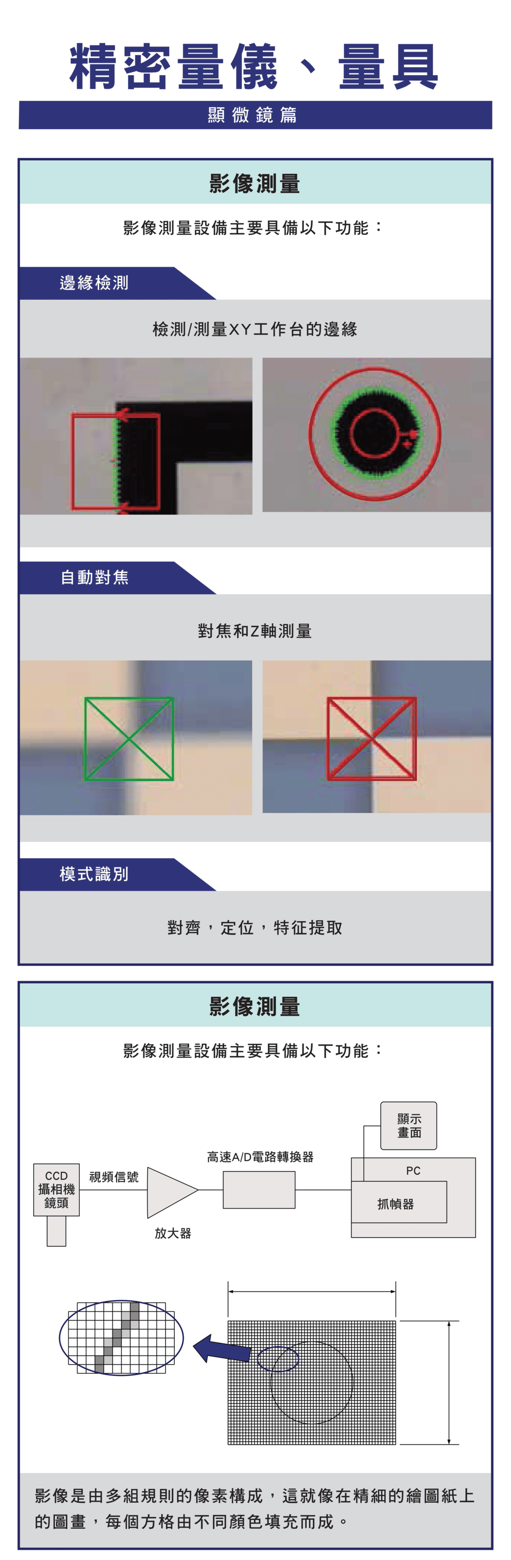
A VMS provides: edge detection, XY in-plane sizing, Z-axis height (auto focus), pattern recognition/feature extraction, and alignment/positioning. The system is built from a CCD, lens, image-processing electronics and a computer — a non-contact method.
2. Image and Pixel Basics
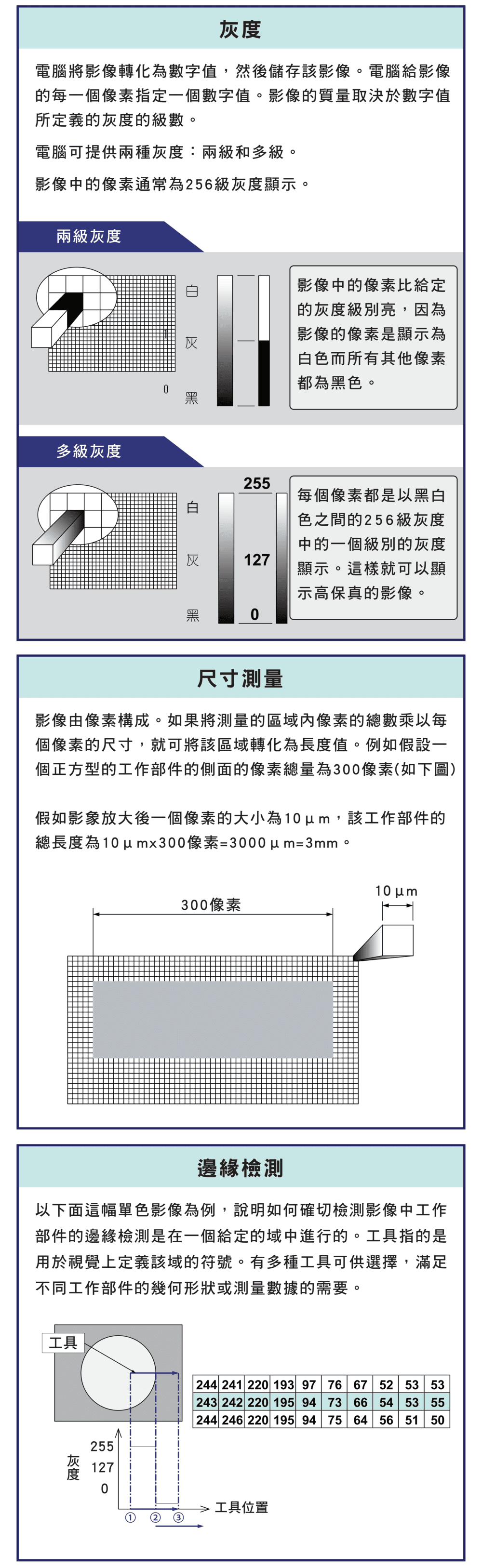
An image is made of pixels, each holding a value; image quality depends on grey levels — either two-level (black/white) or multi-level (usually 256). Richer grey levels give more precise contour and edge determination.
3. Sizing Principle (Key Formula)
The core calculation of vision metrology:
| Item | Content |
|---|---|
| Formula | Actual size = pixel count × single-pixel size |
| Example | 300 pixels × 10 μm = 3 mm |
4. Edge Detection and Sub-Pixel Accuracy
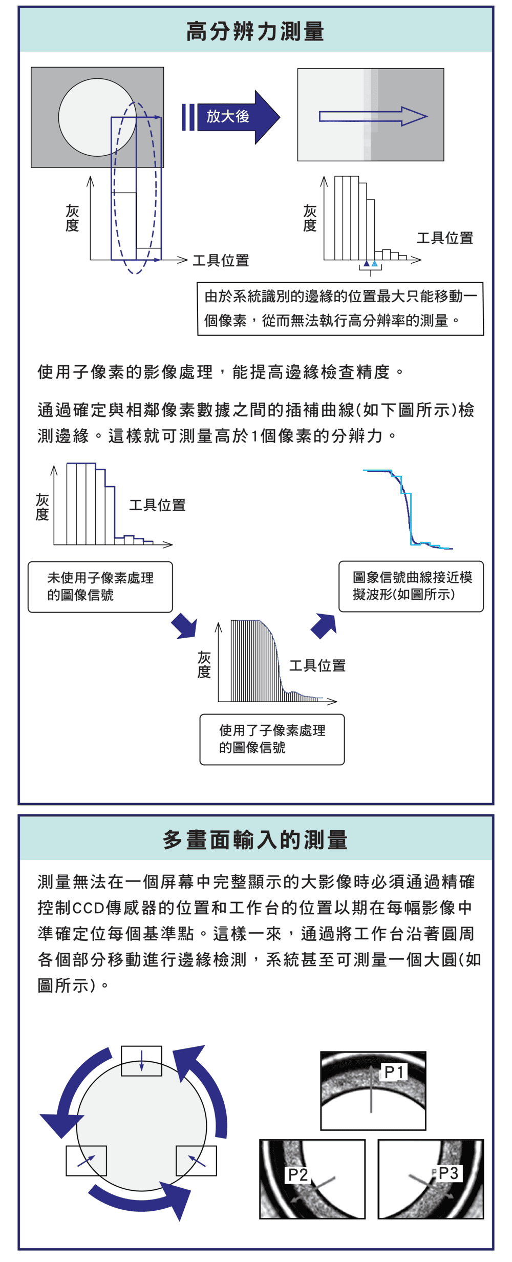
Edge detection reads contour from grey-scale change: pixel variation is analysed within a region of interest (ROI), tools define the measurement area, and it suits varied geometry. Sharper grey change means a clearer edge and more accurate measurement. A traditional edge locates only to a whole pixel; sub-pixel technique fits an interpolation curve to the grey transition to reach below 1 pixel, raising resolution and edge accuracy.
5. Image Stitching
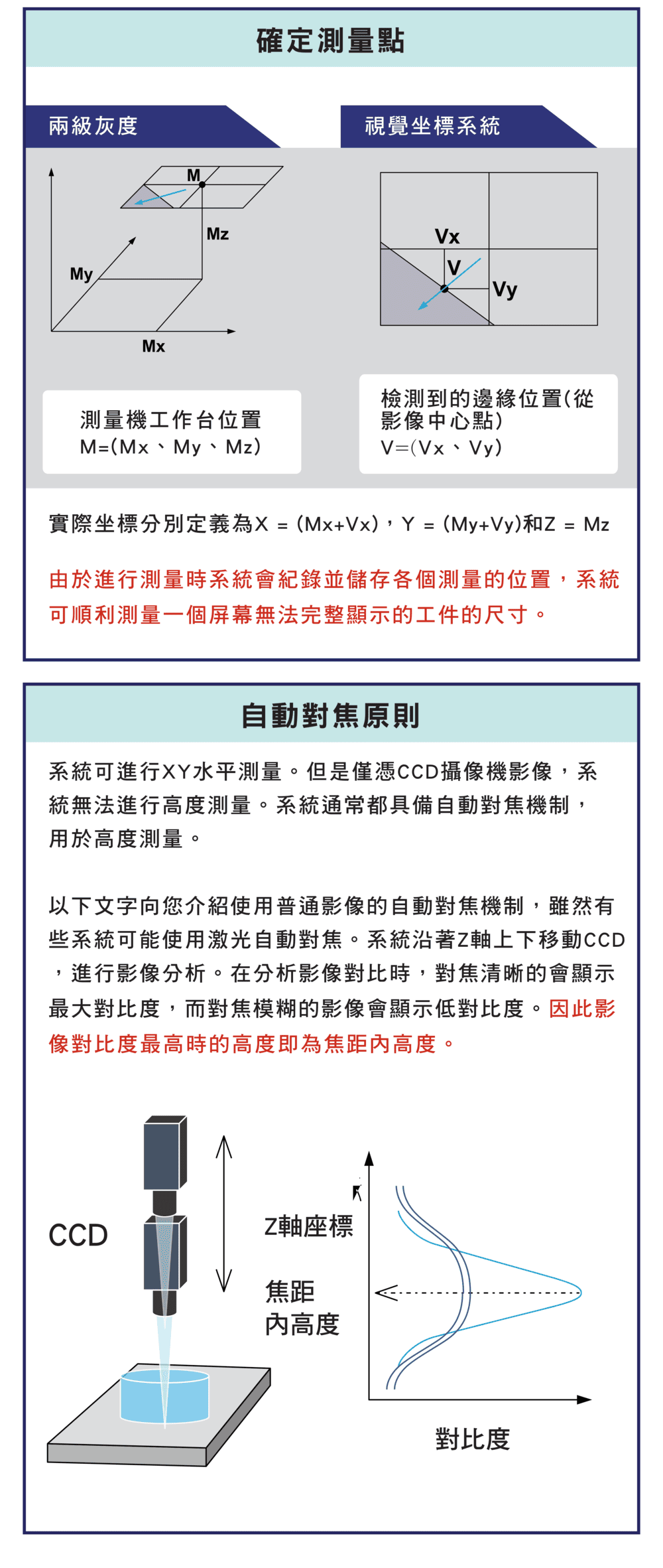
When a part exceeds the field of view, the CCD and stage move to capture images in sections and build a complete model. Used for large workpieces and round or ring-shaped parts.
6. Auto Focus
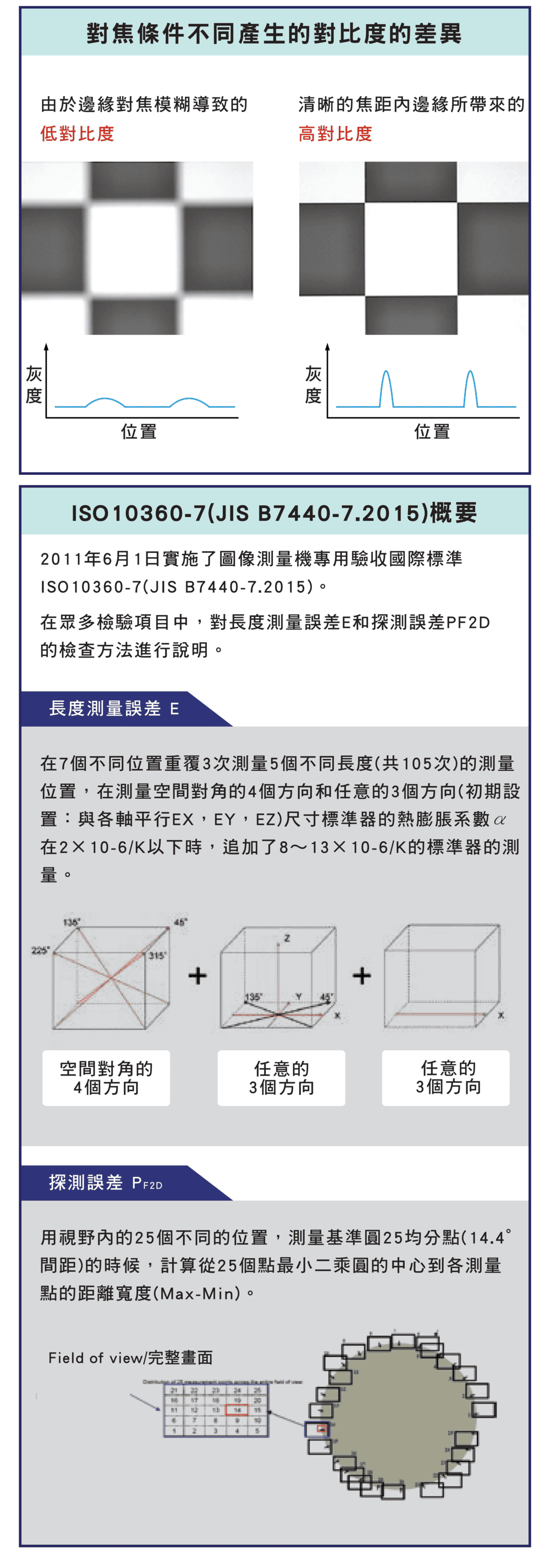
The VMS measures Z-axis height by moving the lens along Z and analysing image contrast. The rule: peak contrast is the focus position; low contrast is blur. This is the key to non-contact height measurement. Focus vs accuracy: blurred edge → low contrast → large error; sharp edge → high contrast → high accuracy.
7. Roundness Harmonics (UPR)
Undulations Per Revolution (UPR) separate roundness error sources: low UPR is mostly form deviation, 3–5 UPR often comes from clamping distortion, high UPR reflects surface texture. For deeper roundness analysis see the Roundness & Cylindricity Guide.
8. Standard (ISO 10360-7)
A VMS conforms to ISO 10360-7, mainly checking length error E and probing error PF2D, using multi-position repeats, multi-direction spatial verification and 25-point circle analysis.
FAQ
Q: Vision system vs CMM?
A VMS measures without contact via CCD imaging — good for in-plane contours, edges, thin or hard-to-touch features; a CMM touches with a probe — good for 3D geometry and deep bores. They complement: vision for planar/thin parts, CMM for solids. See CMM Accuracy & Uncertainty: ISO 10360 Verification Guide for details.
Q: What is sub-pixel accuracy?
A traditional edge sits on an integer pixel; sub-pixel technique fits an interpolation curve to the grey transition to locate the edge below one pixel — effectively raising resolution and accuracy without changing the lens.
Q: How does auto focus measure height?
The lens moves along Z while contrast is analysed; peak-contrast position is the focal plane, and its Z coordinate is the height. Focusing at many points builds a surface height map — all non-contact.
Q: What affects accuracy?
Mainly image sharpness and grey contrast: clearer edge and higher contrast mean less error. Lighting, magnification, single-pixel size and whether sub-pixel is used all matter, so calibrate the pixel scale before measuring.
This article is part of Precision Measurement Complete Guide: Ask What You Are Measuring First, Then Pick the Instrument; that guide shows how the whole topic fits together.
Published: 2026-03-23 | Last updated: 2026-10-20