
Why Round Insert Speeds Come Out Wrong: The Cumulative Effective Diameter Trap
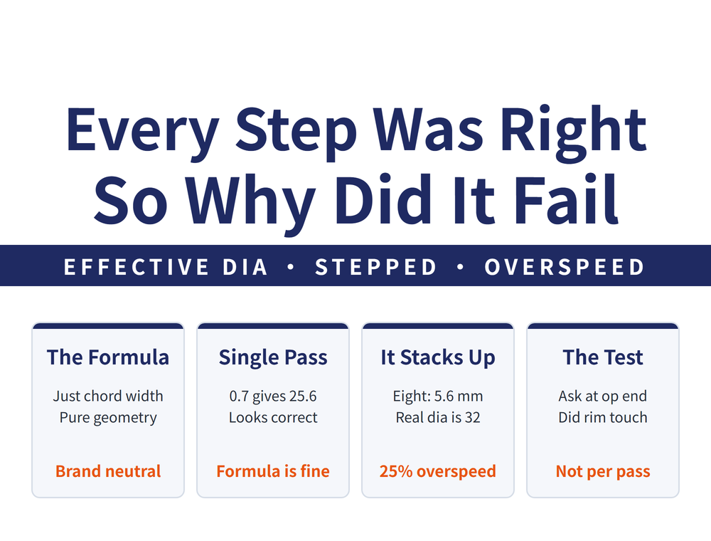
One kind of tool failure is especially hard to diagnose: every step looks correct on its own, and the tool still will not last. Round inserts milling a deep narrow cavity are the classic case. A 0.7mm light depth gives an effective diameter of 25.6mm, and setting the speed from it is correct. But by the eighth step down pass, the contact height accumulated on the side wall has reached the insert radius, what is actually cutting is the 32mm nominal diameter, and the whole job has been running 25% over speed. This article explains the geometry behind the formula and how to spot the cumulative trap.
1. How Effective Diameter Is Calculated, and Why It Is Pure Geometry
The real cutting diameter of a round insert changes with depth of cut. The formula is:
De = D + 2 × √( d × ap − ap² )
| Symbol | Meaning |
|---|---|
| D | Insert centre circle diameter, not the nominal tool diameter, and this is the easiest thing to misread |
| d | Insert diameter |
| ap | Axial depth of cut |
Worth knowing: this is not an empirical fit, it is the half chord width of a circle. The insert is a circle of radius d/2, and at a height ap above its lowest point the half chord width is exactly √(d·ap − ap²).
So De is the outermost diameter genuinely engaged in cutting at that depth. Being pure geometry, it has no range of validity and does not vary by brand.
2. A Neat Consistency: At the Insert Radius, De Converges on the Nominal Diameter
Check it on a round insert cutter with a 20mm centre circle and 12mm inserts, which makes a 32mm nominal diameter:
| Axial depth ap | Effective diameter De | Note |
|---|---|---|
| 0.7 mm | 25.6 mm | Light depth |
| 6 mm, the insert radius | 32.0 mm | Exactly the nominal diameter, 20 plus 12 |
Which means: at a depth equal to the insert radius, the whole cutting portion of the insert is engaged, and effective and nominal diameter become the same number. Turned round, any depth below the insert radius gives a De smaller than nominal, and using the nominal diameter to set speed then runs the tool too slow.
But the real trap goes the other way.
3. 🔴 The Case: Every Step Correct, Tool Life Still Poor
| Item | Detail |
|---|---|
| Workpiece | Solid block of SAE/AISI 4340 steel |
| Operation | Deep narrow cavity with near vertical side walls |
| Tool | Round insert cutter, 20mm centre circle, 32mm nominal, 12mm inserts |
| Strategy | Contour passes stepping down 0.7mm at a time, peeling layer by layer |
| What the customer did | Set conditions per the manufacturer, having already allowed for overhang and effective diameter |
| Result | Very poor tool life |
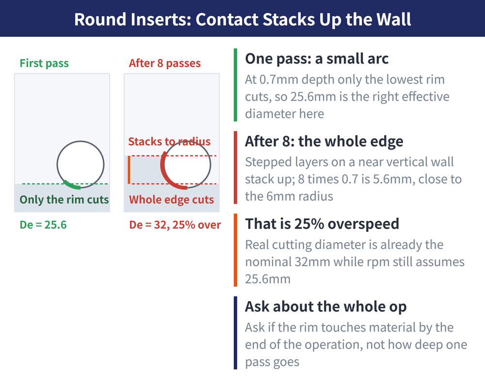
The problem is accumulation. The first pass really does engage only a small part of the cutting edge, but every pass after it brings a fresh length of edge into contact:
By the eighth pass, the accumulated contact height near the side wall is 8 × 0.7 = 5.6 mm,
against a maximum depth of 6 mm, the insert radius. Almost the entire cutting portion is engaged.
| Item | Value |
|---|---|
| Effective diameter as calculated, single pass at ap 0.7 | 25.6 mm |
| Diameter actually cutting after the eighth pass | 32 mm |
| Actual cutting speed divided by the set value | 32 ÷ 25.6 = 1.25 times |
🔴 That is 25% over speed for the whole job, while every single step looks correct in isolation.
4. 🔑 The Test: Ask About the Operation, Not the Pass
What this case really teaches is that the concept of effective diameter is not wrong. What is wrong is treating the contact of one pass as the contact of the whole operation.
| Way of thinking | Gives | Correct? |
|---|---|---|
| Pass thinking: this pass only cuts 0.7mm | De = 25.6 | Formula right, scope wrong |
| Operation thinking: how high the wall contact ends up | De = 32 | This is the one to use |
The test, which generalises to any tool: ask whether the outermost edge of this tool touches material by the end of this operation, not how deep this one pass cuts.
Wherever you have step down passes against a near vertical wall, the contact of successive passes stacks up along that wall, and accumulated contact height is roughly the number of layers times the depth per layer. That is the quantity that decides the effective diameter.
5. ⚠ The Opposite Error Exists Too
On an open face taken in a single light pass, where nothing stacks against a wall, De really is only 25.6, and using the nominal diameter there runs the tool too slow and throws efficiency away for nothing.
The two errors point in opposite directions, but the test is the same one. Look first at whether the geometry accumulates, then decide which diameter to use. For depth limits themselves see [How Deep Can an End Mill Go: Depth Limits for Slotting and Shouldering]; for converting to speed and feed see [End Mill Cutting Conditions Guide]; for the ball nose and bull nose version, see [Effective Diameter for Ball Nose and Bull Nose Tools].
6. Frequently Asked Questions (FAQ)
Q: Which diameter is D in the formula?
The insert centre circle diameter, not the nominal tool diameter. Nominal equals centre circle plus insert diameter, so the two differ by one insert diameter and substituting the wrong one skews the whole calculation.
Q: How do I quickly tell whether contact will accumulate?
Look at the side wall. A near vertical wall stacks each layer's contact into the same height band; an open face or a steeply sloped wall does not. Use nominal diameter for the first case and single pass De for the second.
Q: Should the speed be changed part way through as it accumulates?
In practice most shops set to the final state, the nominal diameter, which is conservative and needs no program change. Staging the speed by layer count is only worth considering when squeezing out the last of the cycle time.
Q: Does this trap only happen with round inserts?
It is most visible there, because their effective diameter varies most with depth. The test is general though: any tool whose effective diameter changes with contact height raises the same question in layered machining.
The case figures are calculated for one particular tool specification and set of conditions, and serve to illustrate the test. For your own application, recalculate from the centre circle and insert size of the tool you are using and consult the tool manufacturer's data.
Last updated: 2026-10-19









