
Tool Wear Guide: Chipping, BUE & Thermal Crack Solutions
Tool wear is a critical factor in CNC machining quality and efficiency. Common types include flank wear, crater wear, built-up edge, chipping and thermal cracking. Each pattern reflects an issue in cutting conditions, material or tool design. Knowing the signature and countermeasure of each helps extend tool life and improve stability.
1. Main Types of Tool Wear
During cutting, tools take on different forms of damage: flank wear, crater (rake-face) wear, built-up edge, chipping, fracture and thermal cracking. These directly affect accuracy and surface quality.
| Wear type | Description |
|---|---|
| Flank wear | Gradual wear from flank-workpiece friction |
| Crater wear | Crater on the rake face from chip flow |
| Built-up edge | Material welded onto the cutting edge |
| Chipping / fracture | Local or full breakage of the edge |
| Thermal cracking | Cracks from cyclic temperature change |
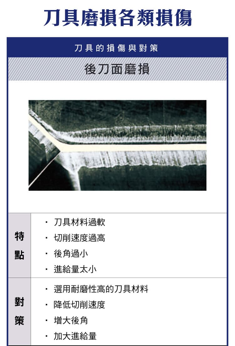
2. Flank Wear
Flank wear is the most common, normal wear mode, worsened by soft tool material, high cutting speed, insufficient clearance angle or too small a feed.
| Causes | Solutions |
|---|---|
| Soft tool material, high speed, low clearance, too small feed | Use wear-resistant grade, reduce speed, increase clearance, raise feed |
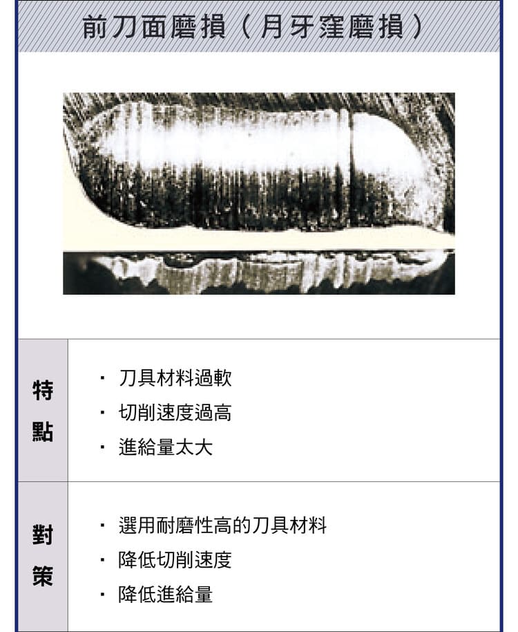
3. Crater Wear (Rake Face)
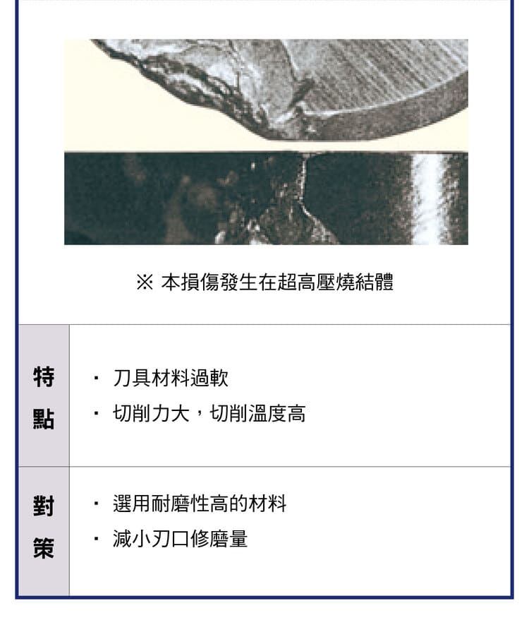
Chips flowing across the rake face at high temperature and pressure form a crescent-shaped crater, often from soft tool material, high speed or excessive feed.
| Causes | Solutions |
|---|---|
| Soft tool material, high speed, excessive feed | Use wear-resistant material, reduce speed, reduce feed |
The table matches the manufacturer chart above, but another tool maker’s handbook lists too low a feed as a cause of crater wear and recommends raising feed — the opposite direction — and neither source states the conditions it applies to. In practice, start with the tool grade and a lower cutting speed; if you do adjust feed, change it in small steps in one direction at a time and check whether the crater improves.
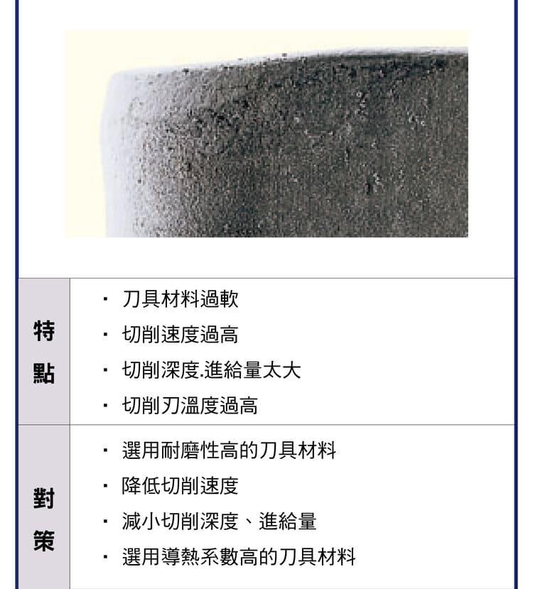
4. Built-Up Edge (BUE)
A built-up edge is workpiece material welded onto the edge, common at low speed, with a dull tool or a sticky material, degrading surface and dimensional stability.
| Causes | Solutions |
|---|---|
| Low speed, dull tool, sticky material | Raise speed, increase rake, use low-affinity (coated) grades |
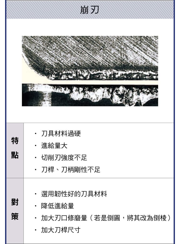
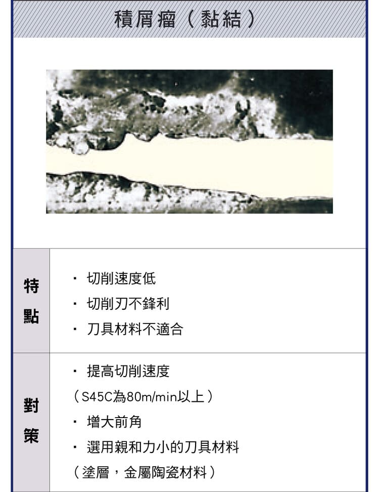
5. Chipping
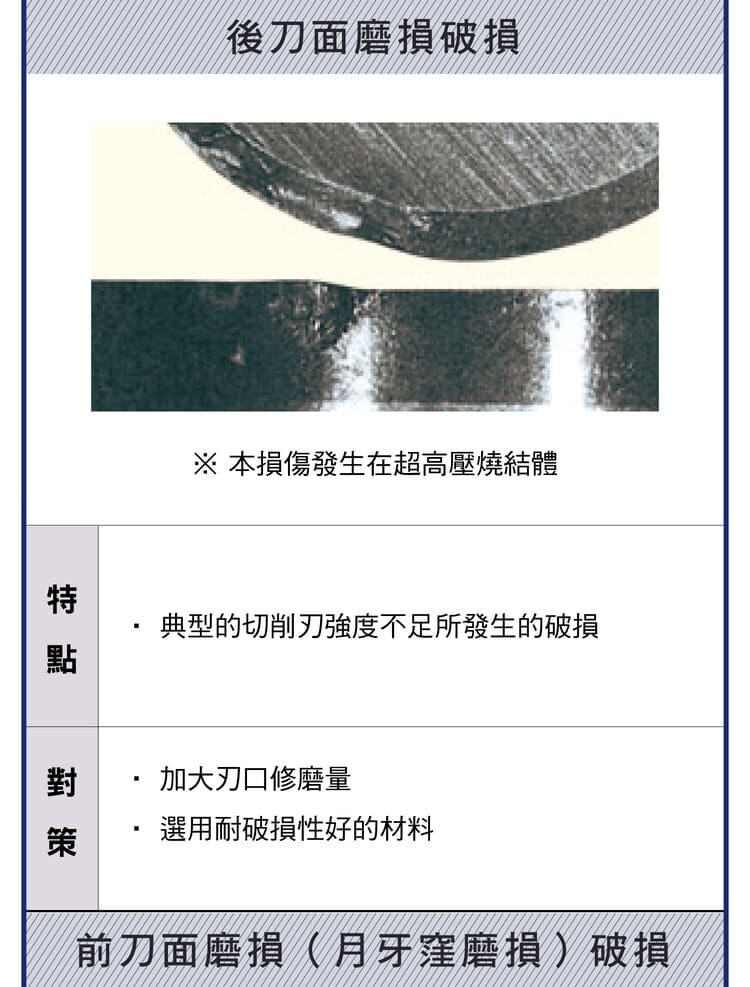
Chipping is small local breakage of the edge, mostly from too hard a grade, excessive feed, insufficient edge strength or low bar rigidity.
| Causes | Solutions |
|---|---|
| Too hard grade, excessive feed, low edge strength, low bar rigidity | Use tougher grade, reduce feed, increase tool size/rigidity, add chamfer or hone |
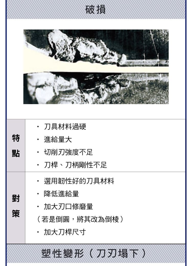
6. Fracture
Fracture is full breakage of the edge or insert — a severe failure — usually from excessive cutting load, insufficient material/tool strength or an unstable tool structure.
| Causes | Solutions |
|---|---|
| Excessive load, low material/tool strength, unstable structure | Reduce load, increase toughness, improve tool geometry |
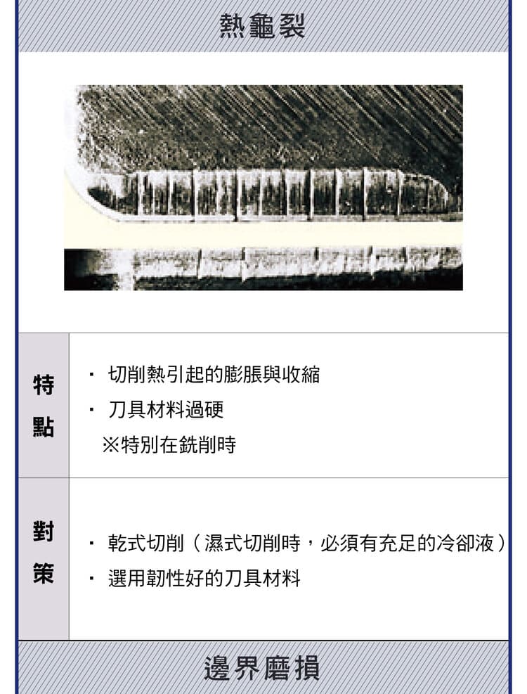
7. Thermal Cracking
Thermal cracking is cracks from repeated thermal expansion and contraction, often with too hard a grade, and most common in interrupted cutting such as milling. Unstable cooling in turning can also cause it.
| Causes | Solutions |
|---|---|
| Cyclic heating/cooling, too hard a grade, interrupted cutting | Use stable cutting, dry or stable cooling, tougher grade |
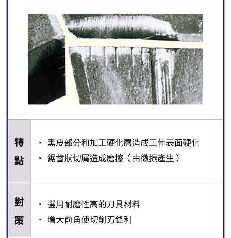
8. Work Hardening & Vibration Wear
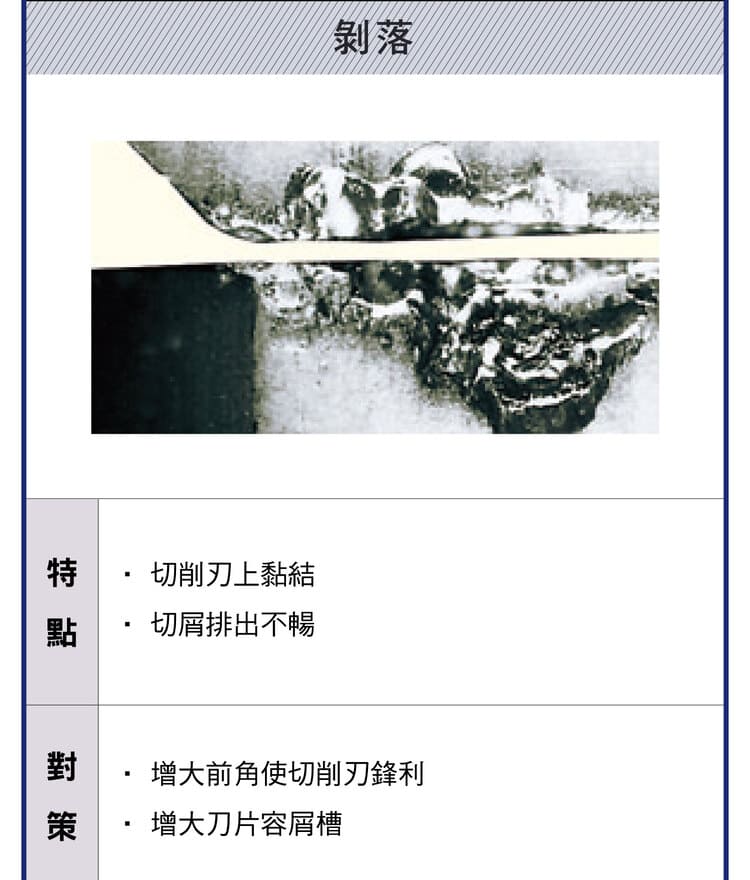
A work-hardened layer or micro-vibration produces a serrated edge wear that hurts surface and dimensional stability.
| Causes | Solutions |
|---|---|
| Work-hardened layer, serrated wear from micro-vibration | Use wear-resistant tools, improve stability, increase rake |
9. CNC Application Notes
Wear-control priorities differ by operation. Calculate actual speed and feed from your material and machine — see the Turning Machining Formulas.
| Operation | Wear-control focus |
|---|---|
| High-speed machining | Watch heat wear and thermal cracks |
| Heavy cutting | Avoid chipping and fracture |
| Finishing | Control flank wear |
Wear patterns are closely tied to tool angles — see the Turning Tool Rake & Clearance Guide; for insert grade selection see the ISO Turning Insert Guide.
FAQ
Q: What if flank wear is too fast?
Flank wear usually comes from too soft a grade, too high a speed or too little clearance. Switch to a wear-resistant grade, moderately reduce speed, increase clearance, and check whether a too-small feed is making the edge rub in the hardened layer.
Q: How do I remove built-up edge?
BUE forms at low speed, with a dull tool or sticky material. Raise the speed above the BUE-forming range, increase rake for a sharper cut, and use a low-affinity coated grade.
Q: Chipping vs fracture — what's the difference?
Chipping is small local edge breakage, linked to excessive feed, too hard a grade or low rigidity; fracture is full insert breakage, a severe failure from excessive load or an unstable setup. Fix the former with parameters and rigidity, the latter by cutting load and raising toughness.
Q: Where does thermal cracking mostly occur?
Thermal cracking comes from cyclic thermal expansion and contraction and is most common in interrupted cutting such as milling. Use stable cutting, dry or stable cooling (avoid hot-cold cycling), and a tougher tool grade.
For the full reading guide on this topic, see Tool Life and Wear: A Complete Reading Guide.
For the full reading guide on this topic, see Turning: The Complete Guide.
Published: 2026-03-25 | Last updated: 2026-10-05









