
What the Feature Control Frame Actually Carves Out in Space: All 13 Tolerance Zones Explained
Reading the symbol is only the first step. Once the frame is filled in, what shape does that tolerance actually carve out in space — a thin slice between two parallel planes, or a cylinder? This guide lists the tolerance zone shape for all 13 geometric characteristics in one table, and pulls out the single point people get wrong most often: whether a φ sits in front of the value decides whether the zone is a circle (or cylinder) or a distance between two parallel planes. To look up a shape, go straight to the first table.
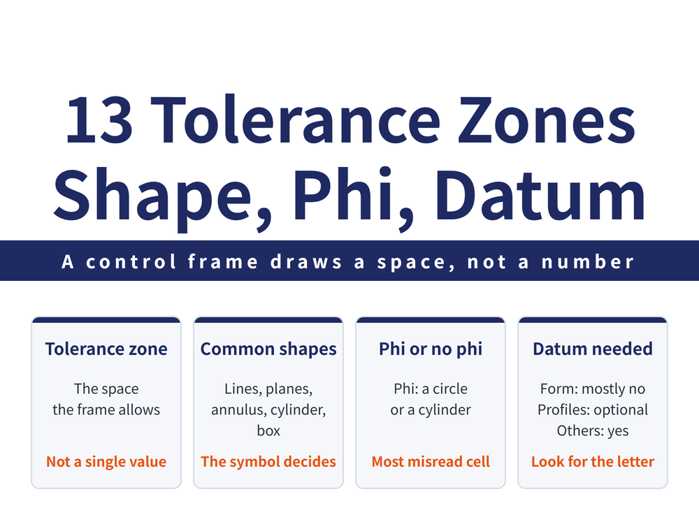
A tolerance zone is the permitted region that a tolerance carves out in space: the actual feature is in spec if it lies entirely inside, and out of spec if any part leaves it. For how the symbols read and how the frame is filled, see Geometric Tolerance Symbols Chart.
1. All 13 Tolerance Zones at a Glance
| Symbol | Name | Shape of the tolerance zone | Does it take φ | Datum needed |
|---|---|---|---|---|
| ⏤ | Straightness | Between two parallel lines, a t1×t2 prism, or a cylinder of diameter t | With φ it is a cylinder | No |
| ⏥ | Flatness | Between two parallel planes | No | No |
| ○ | Roundness | The annulus between two concentric circles | No | No |
| ⌭ | Cylindricity | The annular cylinder between two coaxial cylinders | No | No |
| ⌒ | Profile of a line | Between two envelope lines | No | Either way |
| ⌓ | Profile of a surface | Between two envelope surfaces | No | Either way |
| ∥ | Parallelism | Two parallel lines, a prism, a cylinder or two parallel planes | A line with φ gives a cylinder | Yes |
| ⊥ | Perpendicularity | Same four cases as parallelism, with a right angle instead | A line with φ gives a cylinder | Yes |
| ∠ | Angularity | Between two parallel lines at angle α to the datum (case ① only) | Yes | |
| ⊕ | Position | A circle or sphere, two parallel lines, a prism, a cylinder or two parallel planes | A line with φ gives a cylinder | Yes |
| ◎ | Concentricity | A cylinder of diameter t about the datum axis | Yes, diameter t | Yes |
| ⌯ | Symmetry | Two parallel planes, two parallel lines or a rectangular solid | No | Yes |
| ↗ | Runout | Two parallel planes, two coaxial cylinders, or two circles along the normal | Yes |
2. Whether a φ Is There Is the One Thing to Remember
The same number with and without a φ in front of it gives two completely different zone shapes. This is where drawings are misread most often:
| Written in the frame | The zone is | What that means |
|---|---|---|
⊕ φ0.1 | A cylinder 0.1 in diameter | The axis may shift in any direction as long as it stays inside that cylinder |
⊕ 0.1 (one direction) | Between two parallel lines 0.1 apart | Only the direction the arrow points is controlled |
| Two mutually perpendicular directions (values t1, t2) | A prism of section t1×t2 | Two mutually perpendicular directions, each controlled separately |
The difference is directional symmetry. With φ, the zone is the same in every direction. Without φ, only the direction the arrow points is controlled, and the same part may fail when measured in another direction.
The characteristics that take φ are straightness, parallelism and perpendicularity of a line, position of a line, and concentricity. When the controlled feature is a flat surface (flatness, and parallelism, perpendicularity or angularity of a surface, among others), the zone is two parallel planes and takes no φ; roundness, cylindricity, profile of a surface and radial runout instead have an annulus, an annular cylinder, envelope surfaces or two coaxial cylinders, as in the table above.
3. Form: The Zone Stands on Its Own, No Datum
Straightness, flatness, roundness and cylindricity look only at the feature itself, so there is no datum letter in the frame. The radial difference between the two concentric circles for roundness, and between the two coaxial cylinders for cylindricity, is the tolerance value itself; cylindricity combines axis straightness with roundness of every section. The Geometric Tolerance Symbols Chart describes it as roundness, straightness and parallelism combined; both describe cylindricity, split into a different number of parts, and the zone is the same space between two coaxial cylinders either way.
Straightness is the only form characteristic with three zone shapes: between two parallel lines for a single direction, a t1×t2 prism for two mutually perpendicular directions, and a cylinder of diameter t when φ is added.
For how roundness and cylindricity are actually measured and how to choose between LSC and MZC, see Roundness & Cylindricity Guide.
4. Profile: The Zone Lies Between Two Envelopes
For profile of a line, take every point on the true profile as a centre, draw a circle of diameter equal to the tolerance value, and join the two sets of extreme points into two envelope lines; the actual profile may not go outside them.
Profile of a surface works the same way with spheres instead of circles, giving two envelope surfaces. Both belong to features that may be single or related, meaning they may or may not carry a datum.
5. Orientation: Parallelism and Perpendicularity Each Have Four Datum Cases
Orientation controls the angular relationship between a feature and a datum, so a datum is always required. The zone shape depends on whether the datum is a line or a plane, and whether the controlled feature is a line or a surface:
| Datum and controlled feature | Parallelism zone | Perpendicularity zone |
|---|---|---|
| A line to a datum line | Two parallel lines; a prism for two directions; a cylinder with φ | Two parallel lines t apart, perpendicular to the datum line |
| A line to a datum plane | Two parallel planes t apart, parallel to the datum plane | Two parallel lines; a prism for two directions; a cylinder with φ |
| A surface to a datum line | Two parallel planes parallel to the datum line | Two parallel planes perpendicular to the datum line |
| A surface to a datum plane | Two parallel planes parallel to the datum plane | Two parallel planes perpendicular to the datum plane |
The pattern is clear: when a surface is controlled the zone is two parallel planes; only a line can give a cylinder.
6. Angularity: Only One Datum Case Is Covered Here
The general rule for angularity is that the zone is the area between two parallel lines, or the volume between two parallel planes, set at the specified true angle α to the datum; the tolerance value is the distance between those lines or planes, measured along the arrow direction.
Only a line referenced to a datum line is defined here, in two cases: when the inclined line and the datum line lie in the same plane, the zone is between two parallel lines t apart at angle α to the datum line; when they do not lie in the same plane, the projection of the inclined line onto the plane of the datum line is taken instead, and that projection must lie between the same two parallel lines.
The other three datum cases (a line to a datum plane, a surface to a datum line, a surface to a datum plane) are not covered here; do not assume they follow the structure used for parallelism and perpendicularity.
7. Location: Position, Concentricity and Symmetry
Position controls how far a feature departs from its true location. For a point, the zone is a circle or sphere centred on the true location. For a line there are three cases: two parallel lines each t/2 from the true location for a single direction, a prism for two directions, and a cylinder of diameter t about the true feature line when φ is used. For a surface or median plane, it is two parallel planes each t/2 from the true location.
Concentricity gives a cylinder of diameter t about the datum axis (for a point, a circle of diameter t about the datum point). For symmetry, a median plane is controlled by two parallel planes t apart centred on the plane of symmetry of the two datums; a line or axis is controlled by two parallel lines t apart in one direction, or by a solid whose faces are t1 and t2 apart in two directions.
8. Runout: Three Zones
Runout is the maximum permitted radial variation as the feature turns one revolution about the datum axis, that is, the largest swing of a dial indicator needle; it may take in roundness, concentricity, perpendicularity and flatness errors at the same time.
There are three zones: axial runout lies between two parallel planes t apart perpendicular to the datum axis; radial runout lies between two coaxial cylinders t apart about the datum axis; oblique runout lies between two circles whose radii differ by t along the profile normal, about the datum axis.
Runout forms a class of its own (the composite item) and is not placed under orientation or location.
One boundary worth drawing: the runout in this article is a geometric tolerance on the workpiece drawing; the runout (TIR) of a cutter mounted in a spindle is a different matter — that is a question of machine and clamping condition, not of drawing tolerance, see Tool Runout (TIR).
9. What Is Not Covered Here
Zone shapes that are not stated are left blank in the table rather than filled in by analogy — the shape of the zone decides how the feature is measured and judged, so a wrong guess costs more than a blank.
No standard number is cited in this article. For production drawings and acceptance, follow the drafting standard your company has adopted. For the overall classification of geometric tolerance and maximum material condition, see What Is Geometric Tolerance.
Frequently Asked Questions (FAQ)
Q: What exactly is a tolerance zone?
A tolerance zone is the region a feature control frame carves out in space; the actual feature is in spec if it lies entirely inside. Its shape depends on the characteristic and how it is annotated, and may be two parallel lines, two parallel planes, a cylinder, an annulus or a prism.
Q: What difference does a φ in front of the value make?
With φ the zone is a circle or cylinder and is the same in every direction. Without φ the zone is the distance between two parallel lines or two parallel planes, and only the direction the arrow points is controlled. For the same number, the permitted departure and the measurement method both differ.
Q: Why is only one datum case listed for angularity?
Because only the line-to-datum-line case is fully defined here; the other three datum cases are not covered and should not be assumed to follow the parallelism and perpendicularity structure.
Q: Is drawing runout the same thing as tool runout?
No. Runout on a drawing is a geometric tolerance on the workpiece, measured as the largest variation over one revolution about the datum axis. Tool runout (TIR) is the actual eccentricity of a cutter once mounted in the spindle, a matter of machine and clamping condition. The two cannot be converted into each other.
Published: 2026-08-28 | Last updated: 2026-10-21









