
Tool Runout (TIR): Effects, Measurement and How to Reduce It
Tool runout (TIR) is how far the cutting edge wanders off the true axis of rotation, and it directly drives tool life, surface finish and hole accuracy. When runout is large, each flute cuts an unequal amount; the overloaded flute wears or chips early and drags the whole tool's life down, drilled holes come out oversize and milled surfaces get rough. Runout is not caused by one part — it stacks up from the spindle, the holder taper, the chuck or collet, the tool shank and assembly cleanliness. This guide explains what tool runout is, the problems it causes, where it comes from, how to measure it with a dial indicator, acceptable ranges, and how to reduce it effectively.
1. What is tool runout (TIR)
Tool runout is how far the cutting edge deviates from the axis of rotation as the tool spins. It is most often stated as TIR (Total Indicator Reading): rest a dial indicator on the shank or cutting edge, rotate one full turn, and the maximum reading minus the minimum is the runout. This article deals with radial runout (deviation perpendicular to the axis), which sets how "off-centre" the circle the tip actually traces really is. The smaller the runout, the more concentric and stable the assembled tool runs.
2. What large runout causes
The core problem is unequal chip load per flute: with the centre offset, the flute farther from centre takes a bigger bite and higher load while the others barely cut. A chain of consequences follows:
| Consequence | Why |
|---|---|
| Shorter tool life | The overloaded single flute wears or chips early and scraps the whole tool; the larger the runout, the faster life drops |
| Rougher surface | Uneven feed per tooth in milling leaves marks of varying depth, worsening surface finish |
| Oversize drilled holes | A runout drill cuts a hole larger than its diameter, hurting size and position accuracy |
| Vibration and noise | Unequal cutting force creates regular vibration, affecting size consistency and stressing the spindle |
The smaller the diameter, the more sensitive the tool — the same 0.01mm of runout is a big fraction of a φ2mm cutter but minor on a φ20mm one. So precision small-diameter and high-speed finishing demand especially tight runout.
A number worth remembering: per Sandvik data, every additional 0.01mm of runout can cut tool life by up to 50%, and this matters even more for small-diameter tools.
3. Where runout comes from (it stacks up)
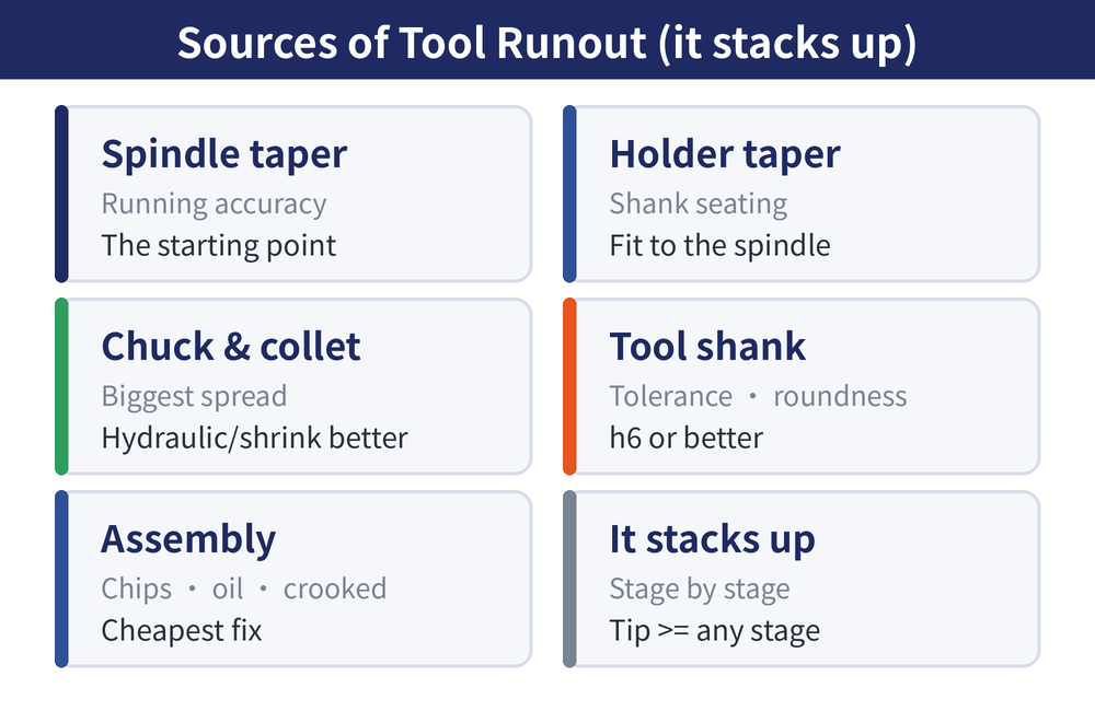
Tool runout is not one part's fault — it accumulates stage by stage from the spindle all the way to the tip. Any stage that is slightly off adds into the total seen at the tip:
| Source | Notes |
|---|---|
| Spindle taper | The spindle's own running accuracy and taper wear are the starting point |
| Holder taper | Accuracy of the holder's taper shank and face, and how well it seats in the spindle |
| Chuck and collet | The biggest spread in concentricity — hydraulic, shrink-fit and precision collets run truer; ordinary collets are worse |
| Tool shank | Shank diameter tolerance and roundness (h6 or better recommended); a bent shank can't clamp true |
| Assembly and cleanliness | Chips or oil in the taper or chuck bore, wrong tightening torque, or a crooked tool all add runout |
Because it stacks, the runout you read at the tip is always equal to or greater than any single stage; fix it stage by stage — the cheapest and most common fix is simply "clean it".
4. How to measure it, acceptable ranges
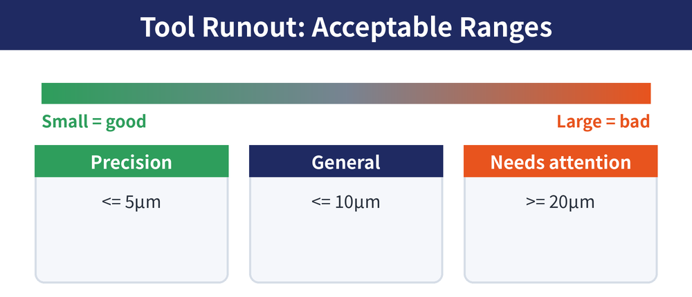
Measure with a lever-type or plunger dial indicator: rest the tip on the shank or near the cutting edge, rotate the spindle one turn by hand or at low speed, and max minus min is the runout (TIR). To capture what actually affects the cut, measure as close to the tip as possible, since a longer overhang magnifies the end runout. Common reference bands:
| Runout (reference) | Positioning |
|---|---|
| ≈ ≤ 0.005mm (5µm) | Precision / high-speed finishing |
| ≈ ≤ 0.01mm (10µm) | Acceptable for general machining |
| ≈ ≥ 0.02mm (20µm) | On the high side — find the cause |
The table is a rough reference; the real limit depends on tool diameter, required accuracy and the tool catalogue, with small-diameter and finishing work being stricter. Always defer to actual measurement and machining requirements.
Also, the holder (clamping end) runout itself should be kept within 0.006mm—tighter than the tool's allowed limit, because holder runout and the tool's own manufacturing tolerance stack up into the final tip runout.
5. How to reduce tool runout
| Action | Notes |
|---|---|
| Clean first | Wipe the spindle taper, holder shank, chuck bore and tool shank; a single chip can cause visible runout — the cheapest fix there is |
| Use a concentric chuck | When accuracy matters, use a hydraulic, shrink-fit or precision collet chuck instead of an ordinary collet |
| Use a good shank | Choose tools with good shank tolerance and roundness (h6 or better); a bent shank can't run true |
| Shorten overhang | Keep the tool stickout as short as the job allows to reduce magnified tip runout |
| Torque correctly, re-index | Tighten to the right torque and seat the tool straight; if runout is high, rotate the tool and re-clamp to find the lowest spot |
| Check for wear | Periodically check the spindle taper and holder taper for wear or scoring; recondition or replace as needed |
Further reading: Tool Holder Clamping Methods Compared, Tool Holder Balance: G2.5 / G6.3, How to Choose a Collet: ER / SK / Pull-Back / Straight.
FAQ
Q: Are tool runout and balance the same thing?
No. Runout (TIR) is a geometric offset of the cutting edge from the axis of rotation, present at any speed and measurable with a dial indicator. Balance is a centrifugal-force problem from asymmetric mass distribution, mainly noticeable at high rpm. Both cause vibration and accuracy issues, but their causes, measurement and remedies differ.
Q: Should I measure runout at the shank or the tip?
It depends on the goal. Measuring at the shank checks chuck and clamping concentricity, but what actually affects the cut is the tip, so to assess real cutting runout measure as close to the cutting edge as possible. The longer the overhang, the more the end runout is magnified, so a reading near the tip reflects the real situation.
Q: How much runout is acceptable?
As a rough guide: general machining is usually fine within about 0.01mm (10µm), precision or high-speed finishing should be within 0.005mm (5µm), and above 0.02mm is high and worth investigating. Small-diameter tools need tighter limits because runout is a larger fraction of the diameter. The real standard follows the tool catalogue and required accuracy.
Q: What is the quickest fix for high runout?
Clean first. Wipe the spindle taper, holder shank, chuck bore and tool shank — a single chip or film of oil can cause visible runout, and this is the cheapest, fastest win. If it is still high after cleaning, check chuck concentricity, shank quality and overhang length, and try re-indexing the tool to find the lowest-runout position.
For the full reading guide on this topic, see Hole Accuracy: A Complete Reading Guide.
This article is part of Tool Holders: The Complete Guide - One End Meets the Spindle, the Other Holds the Cutter; that guide shows how the whole topic fits together.
Published: 2026-07-20 | Last updated: 2026-07-25









