
Height Gauge Guide: Scribing, Comparative Measurement and Common Errors
A height gauge sits on a surface plate and measures height through a column and a slider, and it does two jobs: scribing lines on the workpiece and comparative measurement against a known reference. Like a vernier caliper it violates the Abbe principle, so how it is set up and how far the scriber sticks out eat straight into accuracy. This guide covers four things: the parts and what each one does, how the scriber is mounted, the standard comparative setup (surface plate plus gauge blocks plus scriber), and the three most common error sources — Abbe error, base lift and column squareness, and temperature. For the specification figures, go straight to the EMPE table in section 4.
A note on wording first: the shop floor in Taiwan says height gauge, while catalogues and Japanese-language literature often say height meter. They are the same instrument; this guide uses height gauge throughout.
1. The Parts of a Height Gauge
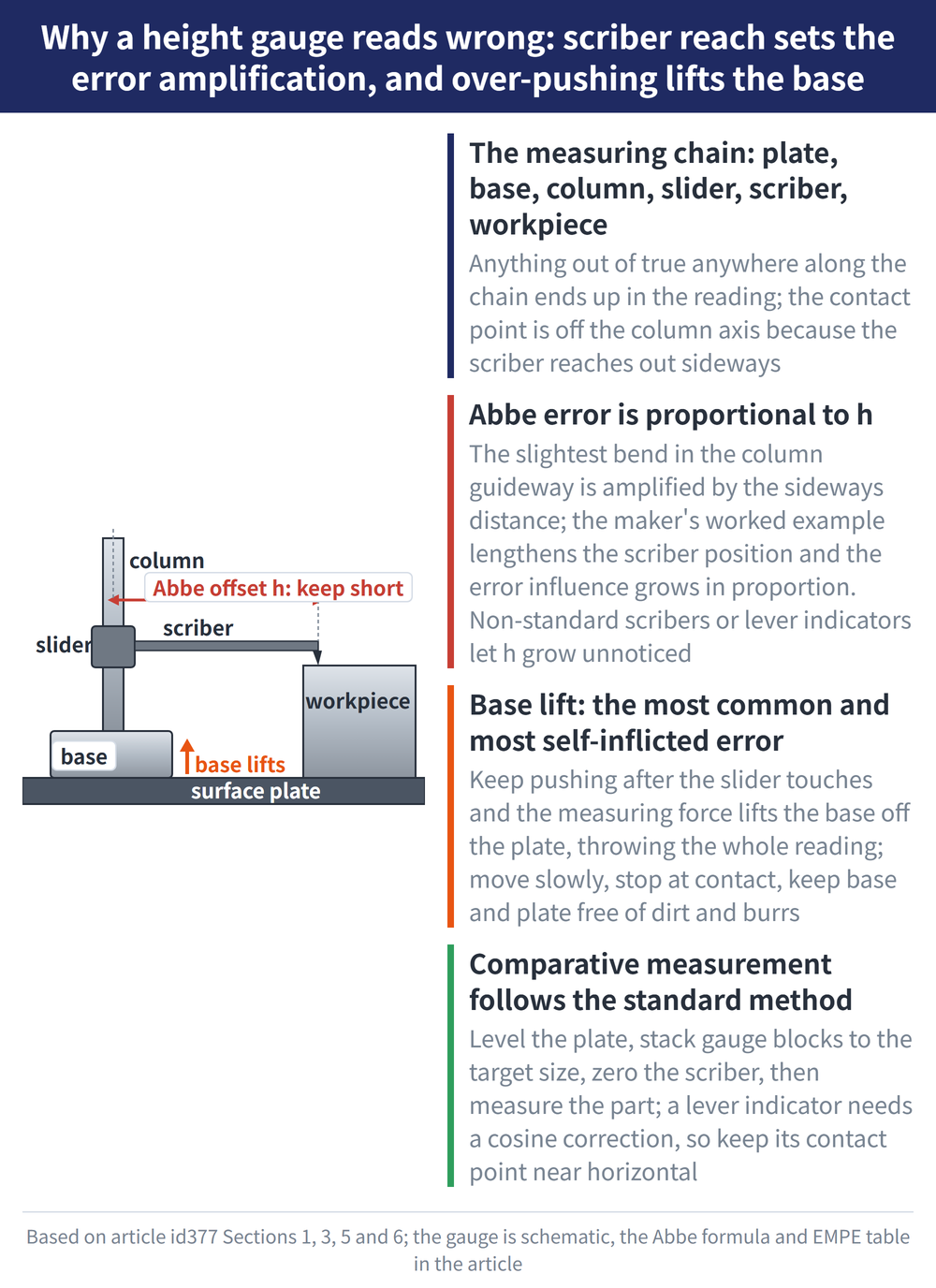
The measuring chain runs surface plate → base → column → slider → scriber → workpiece. Anything out of true anywhere along that chain ends up in the reading:
| Part | What it does |
|---|---|
| Base (base reference surface) | Sits on the surface plate; the height zero of the instrument |
| Column (main scale) | Carries the scale and the guideway; must be square to the base |
| Slider | Travels along the column; the reading is taken from it |
| Drive handle, feed carriage | Coarse and fine feed; over-pushing is an error source |
| Scriber | Clamped to the slider; scribes and contacts the workpiece |
Note that the contact point is not on the axis of the column — the scriber reaches out sideways. That sideways distance is the amplification factor behind the Abbe error in section 5.
2. Scribing: Mounting the Scriber and Setting the Angle
The scriber plays two roles. For plain scribing it is a hard knife edge; for comparative work the shop floor often swaps it for a lever-type dial test indicator. For mounting and reading those, see Dial and Lever Indicator Guide.
There is one general mounting rule: clamp the spindle square to the measured face, because measurement error grows as it tilts. Clamping force matters too — over-tighten it and the spindle no longer moves smoothly. Mounting-hole tolerance and torque limits are set by each maker (Mitutoyo's catalogue, for example, gives ø8G7 and 150 N·cm for a single M5 screw), so follow the catalogue for the instrument you actually own.
Fitting a lever-type indicator adds one more step: its contact point swings rather than travelling in a straight line, so with an angle θ between contact point and direction of displacement the reading needs a cosine correction.
True value L1 = measured value L2 × cosθ
| Angle θ | 10° | 20° | 30° | 40° | 50° | 60° |
|---|---|---|---|---|---|---|
| Correction factor cosθ | 0.98 | 0.94 | 0.87 | 0.77 | 0.64 | 0.50 |
Going from θ = 10° to 30° costs about a tenth of the true displacement for the same reading. Get the contact point close to horizontal; correction is the fallback, not the routine.
3. Comparative Measurement: Surface Plate, Gauge Blocks and Scriber
Comparative measurement is not about reading an absolute height. It is about taking a known size as the reference and measuring the difference. This is not a shop-floor improvisation — it is how the standard itself defines height gauge error.
JIS B 7517 defines the height measurement error this way: gauge blocks on a precision surface plate are gripped by the scriber measuring face, and the gauge size is subtracted from the reading. Copy that on the bench: level the plate, stack blocks to the target size, zero the scriber, then measure the part.
For the gauge block side, see Gauge Block Use and Calibration Guide. Four points when stacking a size:
| Step | Point |
|---|---|
| Selection | Use as few and as thick blocks as possible, starting from the last digit |
| Cleaning | Clean the faces; check for burrs with an optical flat and its fringes |
| Oiling | Apply a trace of oil and wipe until almost no film remains |
| Wringing | Cross thick blocks at 90° and rotate; wring thin ones onto a thick block first |
When a height gauge is used to judge geometric characteristics such as parallelism or step height, see How to Measure Geometric Tolerance.
4. Reading the Specification: EMPE in JIS B 7517
JIS B 7517 was revised in 2018, replacing the old term instrumental error for indication error with the maximum permissible error of indication (MPE). For a height gauge the figure most often quoted is EMPE (height measurement error): the indication error perpendicular to the base measuring face with the contact direction downwards.
The table below gives the EMPE limits for general height gauges in JIS B 7517:2018 (unit: mm):
| Measuring length | Resolution 0.05 | Resolution 0.02 or 0.01 |
|---|---|---|
| 50 and below | ±0.05 | ±0.02 |
| Over 50 up to 100 | ±0.06 | ±0.03 |
| Over 100 up to 200 | ±0.07 | ±0.03 |
| Over 200 up to 300 | ±0.08 | ±0.04 |
| Over 300 up to 400 | ±0.09 | ±0.04 |
| Over 400 up to 500 | ±0.10 | ±0.05 |
| Over 500 up to 600 | ±0.11 | ±0.05 |
| Over 600 up to 700 | ±0.12 | ±0.06 |
| Over 700 up to 800 | ±0.13 | ±0.06 |
| Over 800 up to 900 | ±0.14 | ±0.07 |
| Over 900 up to 1000 | ±0.15 | ±0.07 |
EMPE already includes the error contributed by straightness, measuring-face flatness and reference-face parallelism, so do not add those again. For a specific instrument, follow its inspection certificate or catalogue figure.
5. Common Error 1: Abbe Error and How Far the Scriber Reaches
Like a vernier caliper, a height gauge violates the Abbe principle: the contact point is not in line with the scale axis. The slightest bend in the reference edge of the column guideway is amplified by that sideways distance.
f = h·θ = h × (a / ℓ)
| Symbol | Meaning |
|---|---|
| f | Measurement error |
| h | Contact point to reference guideway distance (Abbe offset) |
| θ | Angular deviation from the bent guideway |
| a / ℓ | Bend a measured over a reference length ℓ |
The formula says one thing plainly: f is proportional to h. The worked example in Mitutoyo's catalogue demonstrates exactly that — taking the scriber mounting position from h = 100 mm to h = 150 mm increases the error influence by a factor of 1.5.
So there is only one thing to do at the bench: keep the scriber reach short. Fitting a non-standard scriber or indicator is where h quietly grows.
6. Common Error 2: Base Lift and Column Squareness
Base lift is the most common one, and the one most often self-inflicted. Keep pushing after the slider has touched the workpiece and the measuring force lifts the base reference surface off the plate, throwing the whole reading off.
Three countermeasures: move the slider slowly and stop the instant it touches; before measuring, check the base reference surface for dirt and burrs (raised spots from knocks); and keep the plate itself clean.
Column squareness is the other one. JIS specifies a squareness tolerance between the base reference surface and the reference edge of the column:
Squareness tolerance = 0.01 + L/1000 (mm), L = measuring length (mm)
At L = 600 mm that works out to 0.61 mm, which looks generous. The reason is that slider tilt and column bend behave differently, so this term contributes relatively little to the final reading. For a specific instrument, follow the catalogue or the standard itself.
7. Common Error 3: Temperature, Hand Heat and Parallax
A height gauge is built from several materials, and workpiece material, room temperature and workpiece temperature can all affect accuracy. The catalogue gives no coefficient of linear expansion for the body, so do not plug in the value for steel and calculate a correction yourself.
Gauge blocks used for comparison are more sensitive still. Handled bare-handed, a steel block expands with body heat and takes tens of minutes to contract and settle again — the actual time depends on size and material. Use a holder or gloves, minimise how long and how much your fingers touch the measuring faces, and allow soak time.
Last comes parallax: always read the scale straight on, since reading at an angle gives the wrong value. For how far to take environment and uncertainty, compare the approach in CMM Accuracy & Uncertainty Guide.
8. Frequently Asked Questions (FAQ)
Q: Are a height gauge and a height meter the same thing?
They are the same instrument. Shop floors in Taiwan say height gauge, while Japanese catalogues and translated literature often say height meter, and the specification standard JIS B 7517 is the same either way. Treat the two terms as interchangeable when buying or checking specifications.
Q: If the scriber is replaced by a lever-type indicator, does the reading need correcting?
Yes. The contact point of a lever-type indicator swings, so with an angle θ to the direction of displacement the true value = reading × cosθ. At θ = 10° the factor is 0.98; at 30° it is only 0.87. The real fix is to set the contact point near horizontal — correction is a remedy, not a routine.
Q: How much error is permitted on a height gauge measuring 300 mm?
Per the EMPE for general height gauges in JIS B 7517:2018, over 200 up to 300 measuring length allows ±0.08 mm at 0.05 resolution and ±0.04 mm at 0.02 or 0.01 resolution. That figure already covers straightness and measuring-face flatness; for a specific instrument, follow the catalogue figure.
Q: Why does the reading keep moving after the scriber touches the part?
Usually base lift. Pushing on after the slider contacts the workpiece lets the measuring force raise the base off the plate. Feed slowly, stop the moment contact is made, and check the base reference surface for dirt or burrs before measuring.
This article is part of Precision Measurement Complete Guide: Ask What You Are Measuring First, Then Pick the Instrument; that guide shows how the whole topic fits together.
Published: 2026-08-28 | Last updated: 2026-08-28









