
How to Measure Geometric Tolerance: Five Inspection Principles and Shop-Floor Practice
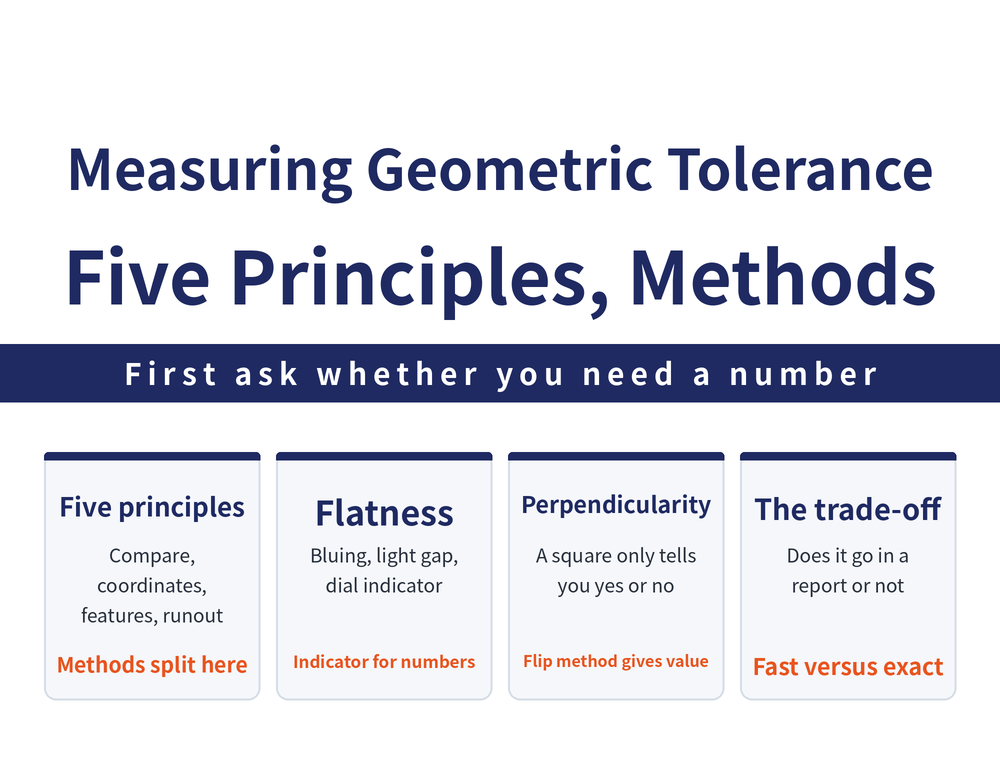
The drawing calls out ⏥ flatness 0.05 and ⊥ perpendicularity 0.03. The part is on the bench — how do you actually measure it? Geometric tolerance inspection rests on five principles: comparison with an ideal feature, coordinate measurement, characteristic-parameter measurement, runout measurement, and control of the virtual condition boundary. This guide covers what each principle implies about method, then works through the flatness, parallelism, perpendicularity and angle checks done most often on the floor, saying for each whether it is qualitative or quantitative. Roundness and cylindricity have their own guide and are not repeated here.
Read the symbols before you talk about measuring. For what the symbol in the frame is called and which feature it governs, see Geometric Tolerance Symbols Chart; for whether the tolerance zone is a cylinder, a pair of parallel planes or a band, see 13 Tolerance Zones Explained. Misread the symbol and you will pick the wrong method — a leader that lines up with the dimension line governs the centre axis, one that does not governs the surface, and the two call for entirely different setups.
1. The Five Inspection Principles: Decide What You Are Comparing Against
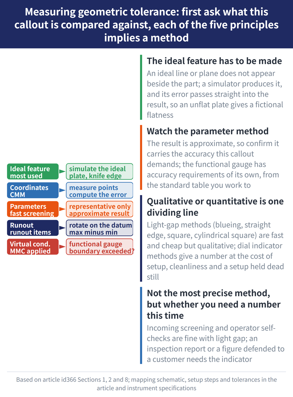
Geometric tolerance is not measured one single way. First ask what this callout is compared against, then choose the instrument:
| Principle | Method | Typical use |
|---|---|---|
| Comparison with an ideal feature | Simulate the ideal line, plane or axis, then compare the actual feature to it | Most used in production |
| Coordinate measurement | Measure coordinate values of the actual feature, then process the data | Coordinate measuring machine |
| Characteristic-parameter measurement | Measure representative parameters only, such as two-point or three-point roundness | Fast screening, approximate result |
| Runout measurement | Rotate the part about the datum axis, take max minus min reading | ↗ Runout |
| Control of the virtual condition boundary | Check with a functional gauge whether the boundary is exceeded | When MMC is applied |
Watch the third principle: a characteristic-parameter result is approximate, so confirm it carries the measurement accuracy this callout demands before you rely on it.
The gauge in the fifth principle has accuracy requirements of its own. The magnitude is a size tolerance two to four grades tighter than the feature checked, with its geometric tolerance at one fifth to one tenth of the feature value — follow the standard table you actually work to.
2. Comparison with an Ideal Feature: the Ideal Has to Be Made
This is the one used most on the floor. An ideal line or plane does not appear next to the part by itself; it is produced by a simulator:
| Ideal feature to simulate | Common simulators |
|---|---|
| Ideal straight line | Fine collimated light beam, knife-edge rule, straight edge |
| Ideal plane | Precision surface plate, optically scanned plane |
| Ideal axis | Precision mandrel, V-block |
One sentence carries this section: the error of the simulator passes straight into your result. If the plate is not flat, the flatness you measure is fiction.
For how to choose the grade of reference artefacts such as plates and gauge blocks, see Gauge Block Selection Guide; for how to read the accuracy figures of a coordinate measuring machine, see CMM Accuracy Guide.
3. ⏥ Flatness: Three Methods, Qualitative to Quantitative
| Method | How it is done | Reading |
|---|---|---|
| Blueing method | Coat the face with a very thin marking medium, move it on a plate | More even and more numerous marks means less error (qualitative) |
| Light-gap method | Set a straight edge on the face, light from the front, watch the gap | No light anywhere means very flat; local light is judged by experience |
| Dial indicator method | Support the part on three jacks, level three points, then sweep the face | The variation in the readings is the flatness error (quantitative) |
The marking medium can be red lead paste or blue oil; what matters is that it is thin. Straight edges come in knife-edge, wide-face and wedge types, and the knife-edge type is the most accurate and the most widely used.
The dial indicator method is the most accurate of the three and hands you an error value directly. Adjust the three jacks while measuring until points A, B and C sit at equal height; the residual height difference is of the order of 0.005 mm (follow your instrument specification or standard table). Keep the plate and the indicator base clean and move the base smoothly, or what you read is dust rather than error.
4. ∥ Parallelism: Both Methods Give You a Number
| Method | How it is done | Reading |
|---|---|---|
| Surface plate and dial indicator | Part and stand both on the plate, pass the whole face under the tip | The variation in the readings is the parallelism error |
| Micrometer | Measure thickness at points a set distance apart, take several points | The difference in thickness is the parallelism error |
The difference is sampling. The plate method captures variation across the whole face; the micrometer captures thickness difference at a handful of points. Use the former where a local high spot matters, the latter on thin parts where end-to-end difference is enough (a lever micrometer also works).
5. ⊥ Perpendicularity: the First Two Groups Are Qualitative Only
Squares work by light gap: fast and cheap, but they give no number:
| Instrument and case | How it is done | Nature |
|---|---|---|
| 90° square (small parts) | One blade against one face, bring the other blade onto the second face | Qualitative |
| 90° square (larger parts) | Part and square both on the plate, one blade against the vertical face | Qualitative |
| Cylindrical square | Stand it on the plate, bring the part slowly up to its generating line | Qualitative, widely used in production |
| Dial indicator | Flip method or precision angle plate method, see the next two paragraphs | Quantitative |
Flip method: measure parallelism first, bring the face gently against a cylindrical gauge pin and read, then flip the part through 180° and read the other face the same way. Half the difference between the two readings is the perpendicularity error. Nothing about the indicator or the pin may shift during the flip.
Precision angle plate method: hold the base of a 90° square against the vertical face and run the indicator tip along one blade to the other. The difference between readings at points a and b, a distance l apart, is the perpendicularity deviation over that distance. Report the distance with the figure, never the figure alone.
6. Angle: the Accuracy Demanded Picks the Instrument
| Accuracy required | Instrument |
|---|---|
| Not particularly high | Bevel protractor or universal bevel protractor |
| High | Sine bar |
| Bevels on small parts | Comparison against an angle gauge |
A sine bar converts a stack height built under its cylinder into an angle. The stack height follows sinα = H / L, where L is the distance between the two cylinder centres and H is the gauge-block stack height. On a sine bar with 200 mm centres, 30° needs H = 200 × sin30° = 100 mm; 20°15′ needs H = 200 × sin20°15′ ≈ 69.223 mm. Round the sine to 0.34612 and you get 69.224 mm — that 1 µm comes from rounding alone, so agree which figure the stack is built to before you wring it.
With the stack in place, read the indicator at both ends of the generatrix: equal readings mean the angle is right. For how to tell from the two readings whether the angle is too large or too small, and the contact-length requirement for taper gauges, see Choosing a Taper Grinding Method: Cone Angle and Part Length Decide, section 6.
7. ○ Roundness and ⌭ Cylindricity: Not Repeated Here
These two are a subject of their own: rotary-axis measurement, the difference between two-point and three-point (V-block) methods, and which reference circle the result is evaluated against (LSC, MZC and so on, with full names in that guide). None of that is the same job as the flat-face checks covered here.
This article points you to the dedicated guide instead — see Roundness and Cylindricity Measurement Guide. The two-point and three-point roundness checks named under the third principle above are set up and interpreted there as well.
8. Qualitative or Quantitative: One Trade-off Runs Through All of It
Stack the sections above and one dividing line appears: light-gap methods (blueing, straight edge, square, cylindrical square) are fast and cheap but qualitative only; dial indicator methods give a number, at the cost of setup, cleanliness, and holding the setup dead still throughout.
So the choice is not about picking the most precise method, it is about whether you need a number this time. For incoming screening and operator self-checks, the light-gap methods are enough. For an inspection report or a figure you will defend to a customer, the indicator goes on. Select according to the accuracy required of the face and the inspection conditions on site.
Step-by-step procedures, attainable instrument accuracy and equipment specifications for each geometric characteristic are not covered here and are not filled in here; for the actual setup and the accept-reject decision, follow the specification sheet of the instrument you use and the inspection standard your company works to.
9. Frequently Asked Questions (FAQ)
Q: Do you need a CMM to measure geometric tolerance?
No. Of the five inspection principles, only coordinate measurement calls for a CMM. Flatness, parallelism and perpendicularity all yield numbers from a precision surface plate and a dial indicator, runout follows the runout principle, and characteristics applied at MMC are checked with a functional gauge.
Q: Do blueing and light-gap results actually count?
They count, but as a qualitative judgement rather than a value. Mark distribution and gap evenness tell you only whether the error is large or small; how to convert them into a figure is not covered here, so any number going into an inspection report must come from the dial indicator method.
Q: Why is the perpendicularity flip method halved?
Because flipping the part through 180° presents the same tilt again in the opposite direction, so the difference between the two readings counts the error twice; half of it is the actual error. This holds only if the indicator and the pin do not move during the flip and parallelism was measured beforehand.
Q: How are roundness and cylindricity measured, and why not here?
Because the site already has a dedicated guide. Setup for roundness and cylindricity, the difference between two-point and three-point methods, and the choice of reference circle are all collected in Roundness and Cylindricity Measurement Guide; this article covers the other geometric characteristics that guide does not reach.
This article is part of Precision Measurement Complete Guide: Ask What You Are Measuring First, Then Pick the Instrument; that guide shows how the whole topic fits together.
Published: 2026-08-28 | Last updated: 2026-10-20









