
Jig Grinding: Sixteen Ways to Run the Planetary Motion, and the Holes It Is For
Jig grinding is the other route to a precision hole: the wheel spins on its own axis while orbiting the hole centre, and machine coordinates place the hole. This article covers the three motions that make up the planetary action, what separates the sixteen methods from one another, and the wheel diameter rule for small bores.
1. The holes jig grinding is for
Most holes are drilled, cored, reamed or bored. Jig grinding takes a different route: a wheel, and the machine coordinate system, bring the hole position and the hole size to specification at the same time. For ordinary internal grinding, where the hole position does not depend on machine coordinates, see Why Internal Grinding Is the Hardest: Get the Wheel and the Quill Right First.
🔑 Where nothing else will do is after hardening. Heat treatment moves both position and size, and once the hardness is there a reamer or boring bar will not cut. Correcting position and size together leaves jig grinding as the only option.
📌 The second case is awkward hole forms — counterbores, tapers, back tapers, slotted bores. Changing tooling does not solve those well; jig grinding solves them by changing the way the wheel runs.
2. Planetary motion: three motions at once
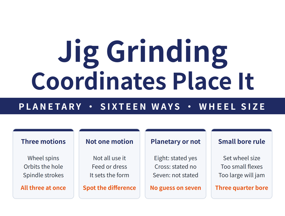
The core action is the planetary motion, and it is three things happening together:
| Motion | What it governs |
|---|---|
| Wheel rotation (high speed) | Cutting speed, so whether it cuts at all |
| Orbit about the hole centre | Hole size; widening the orbit diameter opens the hole |
| Spindle stroke (up and down) | The depth direction, so the whole bore wall is covered |
🔑 Understand those three and the sixteen methods need no memorising. Eight of the sixteen are explicitly listed as using the planetary motion; most of the differences below come down to the feed direction, how the orbit diameter changes, or how the wheel is dressed.
3. Bore methods: through, counterbore, taper, back taper
| Method | What sets it apart |
|---|---|
| Through bore | Spindle stroke plus high speed rotation; on small bores the wheel is 3/4 of bore diameter |
| Counterbore | Vertical feed, working on the edge of the bottom face; best when stock is generous |
| Counterbore, formed | Formed wheel, no vertical feed; best when stock is light |
| Bottom face | Wheel base dressed concave; feed as for a counterbore |
| Taper bore, cylindrical wheel | Wheel tilted by half the included taper angle, vertical feed |
| Taper bore, tapered wheel | Orbit diameter reduces progressively, wheel dressed to the matching angle |
| Back taper | Orbit diameter grows as the spindle descends, wheel dressed to the matching angle |
⚠ The two counterbore methods are a matched pair: generous stock takes the plain method, light stock takes the formed wheel. Choose wrong and the hole still gets made — you just waste either the cycle time or the accuracy.
4. External and contour methods
| Method | What sets it apart |
|---|---|
| External diameter | Orbit diameter reduces progressively, vertical feed |
| External taper | As above, but the wheel taper runs opposite to the work |
| Cross feed | Straight line feed, no planetary motion; suits precision straight-line or contour work |
| Vertical feed | Vertical feed; suits contour work with generous stock |
📌 The direction of the orbit is what separates inside from outside: a bore is ground by growing the orbit diameter, an outside diameter by shrinking it. Same machine, same motion, reversed.
5. Slots, angles and curved surfaces
| Method | What sets it apart |
|---|---|
| Slot side | Rotation with vertical feed; a slotting attachment dresses the wheel to the form required |
| External angled face | Wheel dressed by the slotting attachment; wheel centre must sit above the upper and lower faces of the work |
| Internal angled face | As above, with the added condition that wheel diameter must be less than bore diameter |
| Concave spherical | High speed head on a 45° angle plate, revolving about the spindle |
| Continuous path | An electronic feed system drives a programmed path |
🔑 The sixteen methods fall into three groups by whether the planetary motion is stated: eight are explicitly listed as using it — through bore, external diameter, external taper, counterbore, formed counterbore, both taper bore methods and back taper; only one, cross feed, is explicitly listed as running without it; the other seven (bottom face, vertical feed, slot side, the external and internal angled face methods, concave spherical and continuous path) are not stated either way, so the two tables above list only what sets each apart, and bottom face grinding feeds as for a counterbore. An unusual motion in those seven does not mean they run without the planetary motion the way cross feed does. The methods can be combined.
6. The wheel diameter rule
Through bore grinding carries one concrete rule: on a small bore, the wheel diameter is 3/4 of the bore diameter.
⚠ It is a figure squeezed from both sides. Too small a wheel means a slender quill, too little stiffness, and a bore that opens out into a bell mouth. Too large a wheel leaves no room for the orbit, so it cannot run at all. Three quarters sits between the two limits.
📌 Internal angled face grinding carries the same family of limit — wheel diameter must be under bore diameter or it will not enter. For tracing hole accuracy problems back to their cause, see Cylindrical, Internal and Surface Grinding: Workholding, Motions and Grinding Data.
7. Fix the datum before anything else
Jig grinding lives on coordinate location, so a wrong datum gives a perfectly round hole in the wrong place. Three principles govern location and clamping:
| Principle | Content |
|---|---|
| One datum | Design, process and programming datums all agree |
| One setup | Complete every machined face in a single setup where possible |
| No wasted machine time | Avoid setups that tie up the machine |
📌 Datum selection runs differently at each stage: a rough datum is an unmachined face or the face with least stock, strong and rigid, and is not used twice; a finish datum should follow the design or assembly datum, stay consistent, and sit on an accurate, simply shaped, generously sized surface. For sequencing the part overall, see Manufacturing Process: The Complete Guide - Set the Datum First, Then Sequence, Allowance and Dry Cutting.
8. Frequently Asked Questions (FAQ)
Q: With reamers and boring bars available, why jig grind?
Two situations defeat them. The first is after hardening: heat treatment moves hole position and size, and once the hardness is there neither a reamer nor a boring bar will cut, so correcting both at once falls to jig grinding. The second is awkward hole forms — counterbores, tapers, back tapers and slotted bores — which changing tooling handles badly, while jig grinding handles them by changing how the wheel runs.
Q: What exactly is the planetary motion?
Three motions at once. The wheel spins at high speed on its own axis, which sets cutting speed. The wheel orbits the hole centre, and that orbit diameter sets the hole size, so widening it opens the hole. The spindle strokes up and down so the whole bore wall is covered. Of the sixteen methods, eight are explicitly listed as using this set; what separates the methods is mostly the feed direction, how the orbit diameter changes, or how the wheel is dressed.
Q: What wheel size for a small bore?
Three quarters of the bore diameter. The ratio is squeezed from both sides: a smaller wheel needs a slender quill that lacks stiffness, which opens the bore into a bell mouth, while a larger wheel leaves no room for the orbit and cannot run. Internal angled face grinding carries the same family of limit — the wheel diameter has to be under the bore diameter to enter at all.
Q: Do all sixteen methods use the planetary motion?
No. Eight are explicitly listed as using it: through bore, external diameter, external taper, counterbore, formed counterbore, both taper bore methods and back taper. Only cross feed grinding is explicitly listed as running without it; it uses straight line feed and suits precision straight-line or contour work. The other seven are not stated either way: bottom face grinding feeds as for a counterbore; vertical feed grinding suits contour work with generous stock; slot side grinding uses a slotting attachment to dress the form; the external and internal angled face methods also dress the wheel with the slotting attachment; concave spherical grinding mounts a high speed head on a 45 degree angle plate revolving about the spindle; continuous path grinding follows a programmed route under an electronic feed system. The methods can be combined.
This article is part of Grinding Wheels and Machines: The Complete Guide - Reading the Wheel, Mounting It, Dressing It, and Tracing Defects; that guide shows how the whole topic fits together.
Published: 2026-09-21 | Last updated: 2026-10-24









