
Checking a Machining Center's Accuracy: Three Classes and Five Conditions Before You Measure
Accuracy acceptance on a machining center (a CNC milling machine with automatic tool change) covers three classes: geometric accuracy, positioning accuracy and working accuracy, and the third can only be measured by actually cutting a test piece. This article explains what each class measures, the five conditions that must be met before measuring (if they are not, the numbers do not count), and why the items to be tested have to be agreed when the machine is ordered.
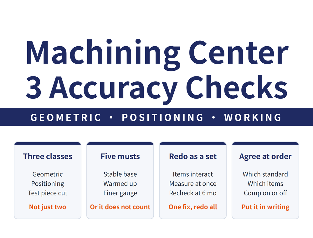
1. Three classes of accuracy, and the third needs a cut
Accepting a machining center means measuring three classes of accuracy. The first two are measured without cutting; the third is not:
| Class | What it measures | Measured with |
|---|---|---|
| Geometric accuracy | Parallelism and squareness of linear motions, axial and radial run-out of rotary motions, position of spindle relative to table | Precision levels, 90° squares, dial indicators, test bars |
| Positioning accuracy | Where each axis actually arrives under control commands | Laser interferometer, or a measuring system of similar accuracy |
| Working accuracy | The accuracy of a test piece machined under finishing conditions | Measuring the finished test piece |
🔑 A common mistake is to treat geometric plus positioning accuracy as the whole job. Working accuracy is a separate, third class; the test conditions for finished test pieces on machining centers are in ISO 10791-7. And the measured positioning accuracy can be used to judge the best accuracy this machine can reach in automatic machining.
The same set of checks for a lathe is in Checking a CNC Lathe's Accuracy and Tracing Its Faults: 18 Tests and the Outside-In Rule; for tracing a conventional lathe's faults back from the workpiece, see Lathe Accuracy and Troubleshooting: Taper, Ripples and Uneven Pitch Point to the Machine.
2. Five conditions before measuring, or the numbers do not count
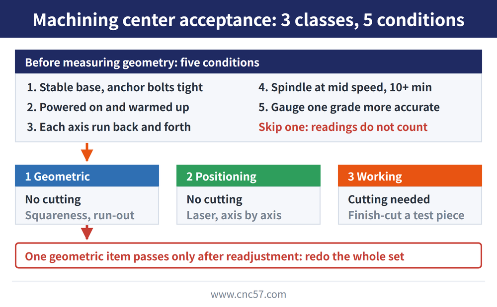
Geometric accuracy is measured only after all five conditions below are met. Skip any one and the readings cannot be trusted:
| # | Condition |
|---|---|
| 1 | The foundation is fully stable and the anchor bolts are tightened |
| 2 | Power is on and the machine has warmed up |
| 3 | Each axis has been run back and forth several times |
| 4 | The spindle has run at medium speed for ten-odd minutes |
| 5 | The gauges are one grade more accurate than the geometric accuracy being measured |
📌 Conditions 2 and 4 deal with heat: geometric accuracy measured on a cold machine does not represent its accuracy at work, so temperature-related items are measured at medium speed once the temperature is stable. For thermal deformation and how long to warm up, see Section 6 of Machine Tool Daily Maintenance: Chips, Lubrication and Accuracy Checks.
3. Measure geometry in one go; one readjustment means redo it all
Many geometric items affect one another, so they are measured in one session after fine adjustment. If any single item passes only after readjustment, the whole geometric acceptance has to be repeated; re-measuring just that item does not count.
| When | What to do |
|---|---|
| Before and after the load test (no load test: after the run-in test) | Measure geometric accuracy both times; the last readings go into the certificate |
| How long to run in | One acceptance rule: 32 hours for a machining center, 16 hours for a general CNC machine |
| During the run-in | No faults or stops; idle time between automatic cycles no more than 1 minute |
| After six months of use | Re-check geometric accuracy once, as the foundation may change over time |
⚠ Run-in hours depend on the standard the machine follows; the contract is what counts.
4. Positioning accuracy has five items, and the other axes must be placed right
Positioning accuracy is measured with a laser interferometer or a similar system, and covers five items:
| # | Item |
|---|---|
| 1 | Positioning accuracy and repeatability of linear motion |
| 2 | Positioning accuracy and repeatability of rotary motion |
| 3 | Reversal error (backlash) of linear motion |
| 4 | Reversal error (backlash) of rotary motion |
| 5 | Return-to-origin accuracy |
📌 When one axis is measured, the moving parts on the other two basic axes should sit as near mid-travel as possible, or wherever they least affect the reading; a sliding spindle or ram used as an auxiliary axis is kept retracted. The method follows ISO 230-2, one axis at a time. Whether two axes moving together hold a true circle is a separate question, checked with a ballbar test; see Hard Milling or EDM: When to Finish a Hardened Mold with a Cutter.
5. Agree the acceptance items when you order
Acceptance follows the standard the machine adopts (ISO 10791-7, CNS or GB), so confirm which one before signing. Not every item in the standard has to be tested; items can be chosen to suit the machine's design, but two things must be settled first:
| To settle | How |
|---|---|
| Which items | With the maker's agreement the user may pick the items that matter, but they must be stated at the time of ordering |
| Compensation on or off | Software can compensate some geometric errors; testing with or without it follows the agreement, and results with compensation must say so |
🔑 When you receive an accuracy report, first check whether it was measured with compensation on or off; if the report does not say, ask the supplier before you sign it off.
6. Periodic checks on a conventional milling machine: four tolerances
⚠ The table below gives the adjustment tolerances for conventional milling machines in periodic maintenance. They are not acceptance values for a machining center and must not be applied to one.
| Check | Conventional mill tolerance | How to measure |
|---|---|---|
| Level | 0.06 mm/m, both directions | Two levels placed on the table |
| Table travel parallelism | Longitudinal 0.02 mm/500 mm, cross 0.02 mm/300 mm | Dial indicator on the arbor, stylus on the table surface, move the table |
| Spindle run-out | 0.01 mm | Dial indicator on the table, stylus on spindle diameter and face, turn by hand |
| Feed dial backlash | 0.127 mm maximum | Turn the feed handwheel gently and read the free play on the dial |
All four follow the same order: measure the current state, compare with the tolerance, adjust only if it is out, then measure again. If level or parallelism is still out after repeated adjustment, hand it to the machine maker for correction.
7. Frequently Asked Questions (FAQ)
Q: Which classes of accuracy are checked when accepting a machining center?
Three: geometric, positioning and working accuracy. The first two are measured without cutting; working accuracy is measured on a test piece machined under finishing conditions, and it is a separate class that the other two cannot replace.
Q: Why warm the machine up before measuring geometric accuracy?
Geometric accuracy measured cold does not represent the machine at work. So power it up and warm it, run each axis back and forth, run the spindle at medium speed for ten-odd minutes, and measure temperature-related items once the temperature is stable.
Q: If one item fails, is it enough to adjust it and re-measure only that item?
No. Geometric items affect one another, so if any item passes only after readjustment, the whole geometric acceptance has to be repeated.
Q: Can the buyer choose the acceptance items?
Yes, with the maker's agreement, and they must be stated at the time of ordering. Also confirm whether the accuracy report was measured with compensation on or off; results taken with software compensation should say so.
This article is part of CNC Machining Fundamentals: The Complete Guide - Know the Machine and Shop, Then Read the Drawing; that guide shows how the whole topic fits together.
Published: 2026-10-25 | Last updated: 2026-10-25









