
Internal Threads Have a Third and Fourth Route: Drill-Threading and Helical Thread-Forming
Internal threading is not limited to cutting and forming. Two newer routes each remove a different slice of process time: helical thread-forming compresses many revolutions of feed into half a turn, and drill-threading swallows the pilot-hole operation itself. Both carry a cost you must accept up front, and both share one non-negotiable machine requirement. This article puts all four routes side by side and states exactly where the cost falls.
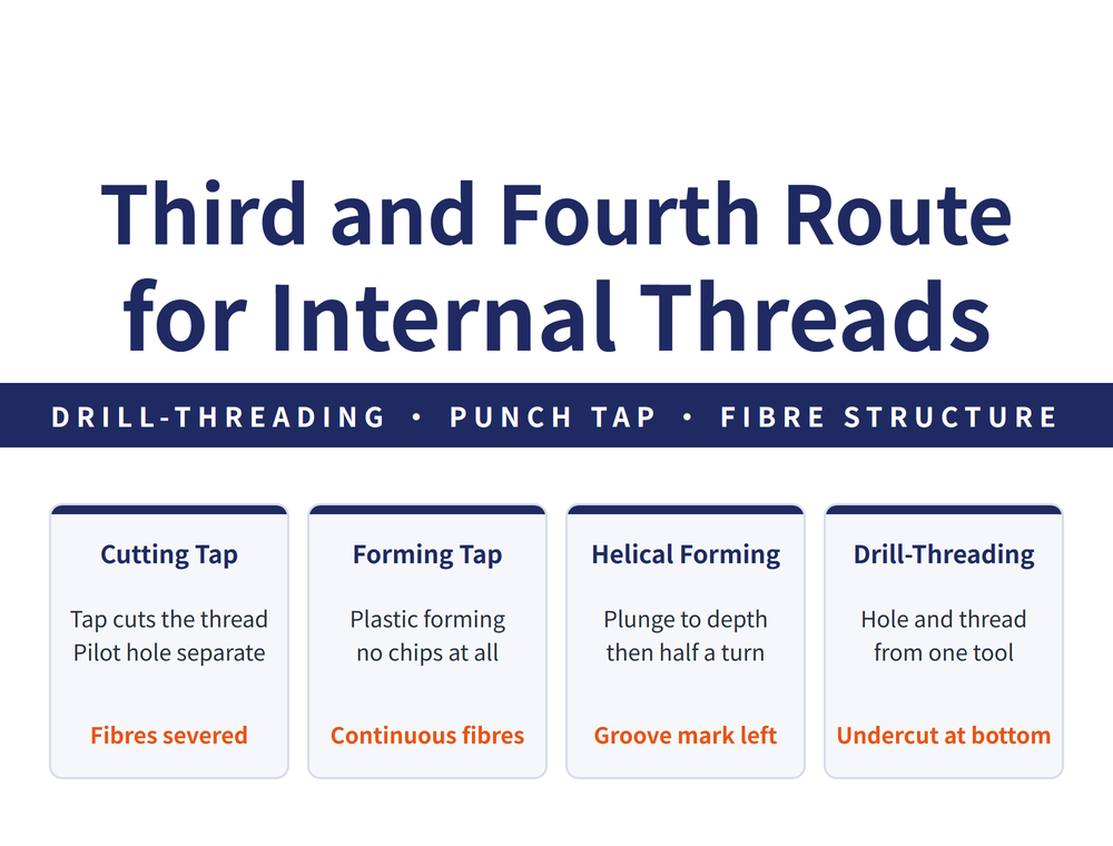
1. All Four Routes, Side by Side
The difference between internal threading methods reduces to one question: how many operations does a single tool absorb? Reading down the table, each route absorbs more than the one above it.
| Route | Pilot hole | How the thread is made | What this route removes |
|---|---|---|---|
| Cutting tap | Separate operation | Tap cuts the material | - (baseline) |
| Cold-forming tap | Separate operation | Plastic deformation, no chips | The chip evacuation problem itself |
| Helical thread-forming | Separate operation | Plunge to depth, then form in half a turn | The back-and-forth multi-revolution feed path |
| Drill-threading | Same tool | Drill point cuts the hole while the forming section behind it makes the thread | The pilot-hole operation, and the tool change in between |
The trade-off between the first two is covered in Cutting Tap vs Forming Tap; this article takes up the other two. For how the operations themselves are sequenced, see Drilling and Tapping Process Guide; for the map of the whole threading line, see Thread Machining Complete Guide.
2. Helical Thread-Forming: Many Revolutions Compressed Into Half a Turn
A conventional tap, cutting or forming, must feed in one pitch per revolution all the way to depth, then unwind out the same way. The tool path equals hole depth divided by pitch, counted twice. Helical thread-forming replaces that with three moves: plunge (straight to depth, no rotation), form (a single half turn completes the thread), and retract (straight out). Half a turn is enough because of a special tooth form plus the helical groove pressed in during the plunge.
The tool itself has three sections: a reinforced punch tooth that presses the groove and steers material flow, a threading section that forms the thread in one motion, and an orientation mark so the tool is clamped in the correct position. Coolant supply is compatible with ordinary taps - both internal coolant and MQL work.
Manufacturer example: for M6 x 15 mm of effective thread depth, the tool path is roughly 1/15 that of a conventional tap, which converts to a threading cycle time saving of up to 75% (manufacturer's stated figure; test conditions and sample size were not given).
The cost is stated in the manufacturer's own table: the thread carries a helical groove mark. That is not a defect - it is the local geometry you trade for path efficiency - but the customer must know in advance that this feature is normal, or it gets rejected at incoming inspection.
3. Drill-Threading: Swallowing the Pilot-Hole Operation
What this route saves is not mainly cutting time, but the tool change. The bottleneck the manufacturer identifies is not how fast the thread is cut; it is the travel and dwell between finishing the pilot hole and bringing the tap in - non-cutting time.
This is worth remembering on its own: when someone claims a time saving, first ask whether it comes out of the main time or the auxiliary time. The two are improved by completely different means.
| Step | What happens |
|---|---|
| 1 Zero position | Tool waits above the workpiece |
| 2 Drill-threading | The drill point cuts the hole while the forming section behind it threads the wall just produced |
| 3 Transition to undercut | At the hole bottom, a relief undercut is produced |
| 4 Reversal point | Spindle reverses |
| 5 Transition back to thread | The forming section re-engages the finished thread |
| 6 Exit along the thread | The tool unwinds along the thread without scoring it |
| 7 Back to zero | Thread complete |
Steps 3 and 4 are not an extra design choice - they are geometrically unavoidable. The drill point sits ahead of the forming section, so when the forming section reaches its deepest point, the drill point is already deeper; and the spindle needs a length free of thread in which to stop and reverse. Both reasons point at the same outcome: the hole bottom must carry a length without a full thread.
The way the manufacturer handles this cost is to show that it falls in a length that was never usable anyway: the undercut length corresponds to the lead-in chamfer length of a conventional tap, and a screw could never engage that length in the first place, so effective engagement length is not reduced. This is a very typical engineering argument - the cost is not eliminated, it is shown to fall inside a length that was already being given away. Evaluate it on those terms; do not simplify it into "no cost".
Manufacturer example: an M6 thread 12 mm deep saves roughly 2 seconds each. The process uses patented technology belonging to Audi AG - it is not the tool maker's own development.
4. Why High-Load Applications Favour Non-Cutting Methods
The four methods do different things to the material, and that difference carries all the way through to how much load the thread will take. The table below is drawn from the TU Dortmund study cited by the manufacturer.
| Method | Material fibre structure | Effect on load capacity |
|---|---|---|
| Cutting tap | Fibres severed; thread profile may carry an angular error | Lower load limit, unfavourable stress distribution, reduced effective contact area |
| Thread milling | Continuous fibres, work-hardened material | Higher strength |
| Conventional cold forming | Continuous fibres, work-hardened material | - (the forming baseline) |
| Helical thread-forming | Continuous fibres, plus one helical groove | Comparable to cold forming |
The key line in that table: the cutting tap is the only one of the four that severs the fibres. That is why aerospace and medical work tends to favour non-cutting methods - not because cutting cannot produce a conforming thread, but because severed fibres are inherently worse for load capacity and stress distribution. Another route that forms rather than cuts is Thread Whirling.
5. Two Questions to Ask Before Anything Else
First, does the machine have synchronous tapping? This is a hard prerequisite, not a recommendation; drill-threading additionally requires the dedicated tool holder from that series. Second, can the design accept the cost? Drill-threading always leaves an undercut at the hole bottom, and helical thread-forming always leaves a groove mark on the thread. If either is unacceptable, there is no point costing the rest.
Once both are cleared, the remaining boundaries:
| Item | Detail |
|---|---|
| Hole type | Drill-threading works in both blind and through holes |
| Workpiece material | The catalogue targets cast aluminium and similar light alloys; do not extrapolate to steel or cast iron |
| Inspection | Thread form conforms to DIN ISO 965 and can be checked with commercial thread limit gauges to DIN ISO 1502 - no special gauging required |
| Strength | The manufacturer reports that first tests show strength at least equal to a conventional thread; test conditions and sample size were not given, so treat it as a stated figure |
| Flexibility | The more operations one tool absorbs, the more tightly it is locked to one part specification; change the size and it is a different tool |
In other words, both routes earn their keep on high volumes of one repeated specification. For low-volume, high-mix work, a cutting or forming tap is usually still the better economics. For the selection baseline see Form Tap Complete Guide, and for pilot hole sizes see the Tap Drill Size Chart.
6. Frequently Asked Questions (FAQ)
Q: Is the groove mark left by helical thread-forming a defect?
No. It is a normal feature of the method, listed by the manufacturer under "special characteristics". Tell the customer in advance, or it will be rejected at incoming inspection.
Q: Drill-threading leaves a length without thread at the hole bottom. Does the joint hold?
The manufacturer states that this length corresponds to the lead-in chamfer of a conventional tap, which a screw could never engage anyway, so effective engagement length is unchanged. Check that argument against your own engagement requirement rather than reading it as "no cost".
Q: Can a standard 3-axis machining centre run these directly?
Only if it has synchronous tapping capability, which is a hard prerequisite. Drill-threading also needs the dedicated holder from that series. If either is missing, there is no point evaluating the savings.
Q: Do these work on steel or cast iron?
The catalogue targets cast aluminium and similar light alloys, and the worked example is in a light alloy. It is not stated whether steel or cast iron is covered, so confirm with the supplier and run a small trial rather than extrapolating from light-alloy results.
Published: 2026-09-08 | Last updated: 2026-10-31









