Tool Holder Taper Guide: BT, NT & Morse Taper (MT)
Tool holder taper specs are a core standard affecting tool accuracy and rigidity in CNC machining. The common systems are BT, NT and Morse taper (MT), differing in structure, drawbar retention and application. This guide covers BT, NT and MT holder types, the 7/24 taper ratio and key dimension symbols, to help engineers match holder and spindle for better accuracy and efficiency.
1. What a Holder Taper Is
The taper is the connection between tool and spindle; taper-face contact gives precise location, rigid clamping and fast tool changes. Three common standards:
| Standard | Note |
|---|---|
| BT (MAS 403) | Japanese MAS standard; most common on CNC |
| NT (JIS) | Japanese industrial standard; more traditional |
| MT (Morse taper) | Self-holding; for drills, lathes, manual gear |
2. The 7/24 Taper Ratio
BT and NT use a 7/24 taper — 7 units of diameter change over 24 units of length. This steep, non-self-holding taper is clamped by a drawbar, balancing locating accuracy with quick removal — the common interface for high-speed spindles. Morse taper (MT) is a smaller, self-holding taper that locks by friction and needs no drawbar.
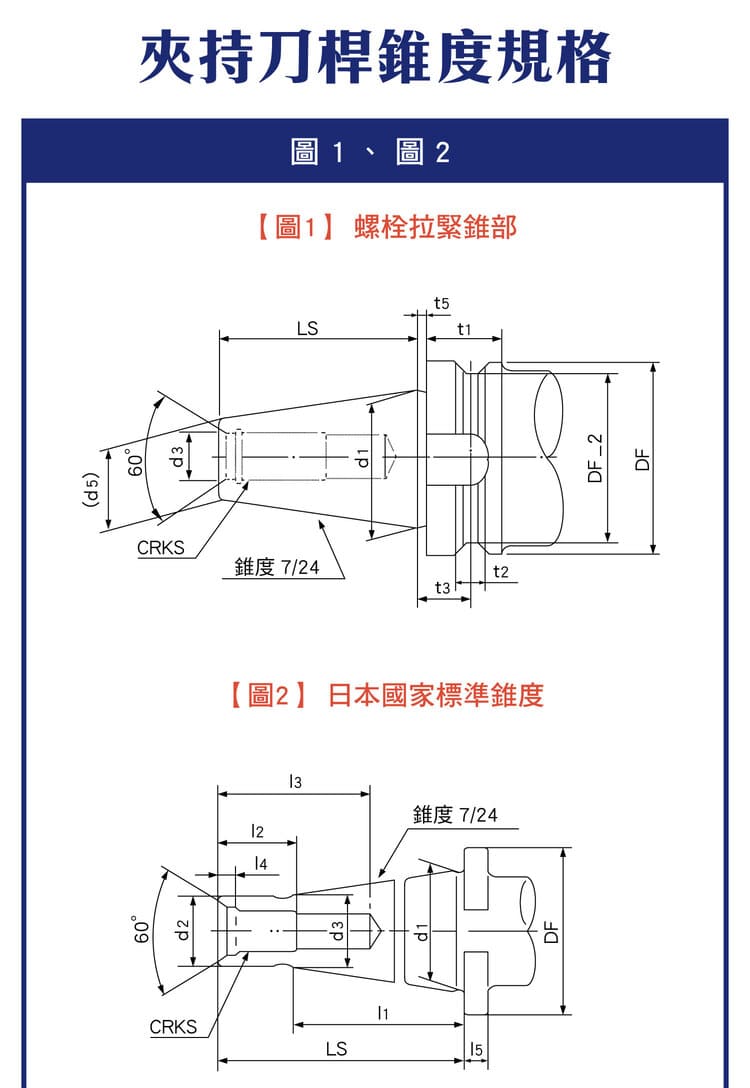
3. BT Holder Specs (Drawbar Retention)
BT is the most common CNC standard — symmetrical, stable at high speed, retained by a drawbar. Common sizes: BT30 / BT40 / BT50 / BT60.
| Symbol | Meaning |
|---|---|
| DF | Holder flange dia |
| d1 | Taper diameter |
| LS | Effective length |
| CRKS | Drawbar thread |
Drawbar thread examples (reference): BT40 → M16, BT50 → M24. Use the spec drawing for exact sizes.
Table 1 - BT drawbar taper (fig. 1)
| Size | DF | DF_2 | t1 | t2 | t3 | t5 |
|---|---|---|---|---|---|---|
| BT35 | 53 | 43 | 20 | 10 | 13.0 | 2 |
| BT40 | 63 | 53 | 25 | 10 | 16.6 | 2 |
| BT45 | 85 | 73 | 30 | 12 | 21.2 | 3 |
| BT50 | 100 | 85 | 35 | 15 | 23.2 | 3 |
| BT60 | 155 | 135 | 45 | 20 | 28.2 | 3 |
| Size | d1 | d3 | LS | CRKS | d5 |
|---|---|---|---|---|---|
| BT35 | 38.1 | 13 | 56.5 | M12×1.75 | 21.62 |
| BT40 | 44.45 | 17 | 65.4 | M16×2 | 25.3 |
| BT45 | 57.15 | 21 | 82.8 | M20×2.5 | 33.1 |
| BT50 | 69.85 | 25 | 101.8 | M24×3 | 40.1 |
| BT60 | 107.95 | 31 | 161.8 | M30×3.5 | 60.7 |
⚠ The catalogue prints the BT45 CRKS as M20×25. A 25 mm pitch does not exist, and the rest of the series runs M12×1.75, M16×2, M24×3, M30×3.5, so this table gives M20×2.5 and records the printed value here so you can reconcile it against the catalogue you are using.
Dimensions in mm; the symbols are located on the drawing above. Values are taken from the tool holder taper page of the Mitsubishi general catalogue (p.1851), to the JIS B 6339 / MAS 403 system; for purchasing, use the model page of the maker you are actually buying from.
4. NT Holder Specs (JIS)
NT is a more traditional standard, common sizes NT30 / NT40 / NT50 / NT60. It is asymmetric and relies more on the drive key for torque, suiting traditional machines.
Table 2 - NT JIS national taper (fig. 2)
| Size | d1 | d2 | LS | l1 | CRKS metric | CRKS Whitworth |
|---|---|---|---|---|---|---|
| NT30 | 31.75 | 17.4 | 70 | 50 | M12 | W 1/2 |
| NT40 | 44.45 | 25.3 | 95 | 67 | M16 | W 5/8 |
| NT50 | 69.85 | 39.6 | 130 | 105 | M24 | W 1 |
| NT60 | 107.95 | 60.2 | 210 | 165 | M30 | W 1¼ |
| Size | l2 | l3 | d3 | l4 | DF | l5 |
|---|---|---|---|---|---|---|
| NT30 | 24 | 50 | 16.5 | 6 | 50 | 8 |
| NT40 | 30 | 70 | 24 | 7 | 63 | 10 |
| NT50 | 45 | 90 | 38 | 11 | 100 | 13 |
| NT60 | 56 | 110 | 58 | 12 | 170 | 15 |
Dimensions in mm; the symbols are located on the drawing above. Values are taken from the tool holder taper page of the Mitsubishi general catalogue (p.1851), to the JIS B 6339 / MAS 403 system; for purchasing, use the model page of the maker you are actually buying from.
5. Morse Taper (MT)
Morse taper is mainly for drills, lathes and manual equipment — a self-holding taper needing no drawbar, commonly MT1–MT7. It locks by taper friction for quick mounting, but rigidity and high-speed balance are below the 7/24 system.
6. Tang vs Drawbar-Threaded Shanks
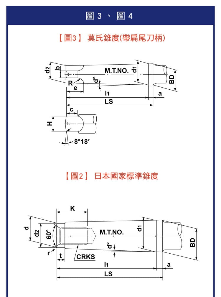
Morse shanks come in two end types:
| End type | Use |
|---|---|
| Tang | For manual equipment; prevents rotation |
| Drawbar-threaded | Takes a drawbar for stronger retention |
Table 3 - Morse taper, tang shank (fig. 3)
| Morse taper no. | d1 | a | BD | d2 | H | l1 |
|---|---|---|---|---|---|---|
| 0 | 9.045 | 3 | 9.201 | 6.104 | 6 | 56.5 |
| 1 | 12.065 | 3.5 | 12.240 | 8.972 | 8.7 | 62.0 |
| 2 | 17.780 | 5 | 18.030 | 14.034 | 13.5 | 75.0 |
| 3 | 23.825 | 5 | 24.076 | 19.107 | 18.5 | 94.0 |
| 4 | 31.267 | 6.5 | 31.605 | 25.164 | 24.5 | 117.5 |
| 5 | 44.399 | 6.5 | 44.741 | 36.531 | 35.7 | 149.5 |
| 6 | 63.348 | 8 | 63.765 | 52.399 | 51.0 | 210.0 |
| 7 | 83.058 | 10 | 83.578 | 68.185 | 66.8 | 286.0 |
| Morse taper no. | LS | d | c | e | R | r |
|---|---|---|---|---|---|---|
| 0 | 59.5 | 3.9 | 6.5 | 10.5 | 4 | 1 |
| 1 | 65.5 | 5.2 | 8.5 | 13.5 | 5 | 1.2 |
| 2 | 80.0 | 6.3 | 10 | 16 | 6 | 1.6 |
| 3 | 99 | 7.9 | 13 | 20 | 7 | 2 |
| 4 | 124 | 11.9 | 16 | 24 | 8 | 2.5 |
| 5 | 156 | 15.9 | 19 | 29 | 10 | 3 |
| 6 | 218 | 19 | 27 | 40 | 13 | 4 |
| 7 | 296 | 28.6 | 35 | 54 | 19 | 5 |
Dimensions in mm; the symbols are located on the drawing above. Values are taken from the tool holder taper page of the Mitsubishi general catalogue (p.1851), to the JIS B 6339 / MAS 403 system; for purchasing, use the model page of the maker you are actually buying from.
Table 4 - Morse taper, drawbar-threaded shank (fig. 4)
| Morse taper no. | d1 | a | BD | d | d2 | l1 |
|---|---|---|---|---|---|---|
| 0 | 9.045 | 3 | 9.201 | 6.442 | 6 | 50 |
| 1 | 12.065 | 3.5 | 12.240 | 9.396 | 9 | 53.5 |
| 2 | 17.780 | 5 | 18.030 | 14.583 | 14 | 64 |
| 3 | 23.825 | 5 | 24.076 | 19.759 | 19 | 81 |
| 4 | 31.267 | 6.5 | 31.605 | 25.943 | 25 | 102.5 |
| 5 | 44.399 | 6.5 | 44.741 | 37.584 | 35.7 | 129.5 |
| 6 | 63.348 | 8 | 63.765 | 53.859 | 51 | 182 |
| 7 | 83.058 | 10 | 83.578 | 70.052 | 65 | 250 |
| Morse taper no. | LS | t | r | CRKS | K |
|---|---|---|---|---|---|
| 0 | 53 | 4 | 0.2 | — | — |
| 1 | 57 | 5 | 0.2 | M6 | 16 |
| 2 | 69 | 5 | 0.2 | M10 | 24 |
| 3 | 86 | 7 | 0.6 | M12 | 28 |
| 4 | 109 | 9 | 1.0 | M16 | 32 |
| 5 | 136 | 9 | 2.5 | M20 | 40 |
| 6 | 190 | 12 | 4.0 | M24 | 50 |
| 7 | 260 | 18.5 | 5.0 | M33 | 80 |
Dimensions in mm; the symbols are located on the drawing above. Values are taken from the tool holder taper page of the Mitsubishi general catalogue (p.1851), to the JIS B 6339 / MAS 403 system; for purchasing, use the model page of the maker you are actually buying from.
7. Reading the Dimension Symbols
Spec drawings use: d1/d2/d3 (segment diameters), l1/LS (lengths), DF (flange dia), t1–t5 (structural sizes). These set spindle compatibility, tool stick-out and rigidity — confirm them together with the spindle interface when selecting.
8. CNC Selection Guide
| Machining type | Suggested holder | Advantage |
|---|---|---|
| High-speed | BT holder | Symmetrical, well balanced |
| Traditional | NT holder | Stable and durable |
| Drilling / simple gear | Morse taper (MT) | Self-holding, quick change |
For lathe-side holders see the Turning Tool Holder Guide and Boring Bar Guide.
FAQ
Q: Are BT and NT holders interchangeable?
Not directly. Though both are 7/24 tapers, the drawbar spec and structure differ (BT symmetrical; NT asymmetric, key-driven) and spindle interfaces differ. Match the holder system to the machine spindle spec.
Q: What does a 7/24 taper mean?
7/24 is the taper ratio — 7 units of diameter change per 24 units of length. It is a steep, non-self-holding taper clamped by a drawbar, giving both locating accuracy and quick release — the common BT/NT high-speed interface.
Q: Why does Morse taper need no drawbar?
Morse taper (about 1.4°–3°) is self-holding — taper friction alone locks it, so no drawbar is needed. It mounts quickly with a simple structure, but rigidity and high-speed balance trail the 7/24 system; it's mainly for drilling and manual gear.
Q: What drawbar thread does BT40 use?
BT40 commonly uses an M16 drawbar and BT50 an M24 (reference). Actual threads vary by brand and drawbar type, so verify the spindle and drawbar spec drawing before buying.
This article is part of Tool Holders: The Complete Guide - One End Meets the Spindle, the Other Holds the Cutter; that guide shows how the whole topic fits together.
Published: 2026-03-25 | Last updated: 2026-07-25