
Regrinding a Floating Boring Tool: Three Angle Blocks and the Precision Route
A floating boring tool is the turner's old friend for finishing holes, and it carries a lot of angles. The traditional way means swinging a vice around on a tool grinder for every one of them. This guide offers two routes: a simple method that freezes the angles into three home-made blocks so the vice never moves, and the precision route to Ra0.1μm, including how one sleeve switches between the cutting taper and the back taper.
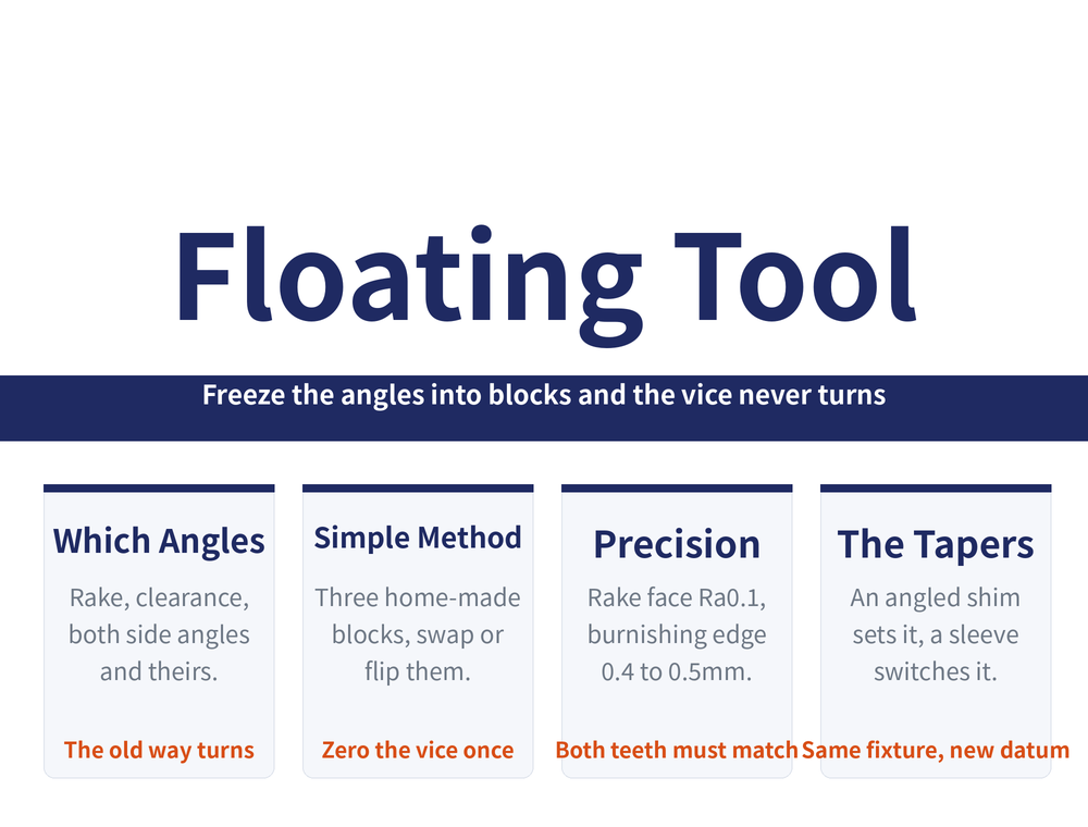
1. Which angles a floating boring tool needs
A floating boring tool finishes holes on a lathe, and the geometry to be ground covers the rake angle, the primary clearance, both side angles and the clearance behind each of them. There are many of them and they interact, which is exactly why the tool is awkward to grind — the traditional route uses a two- or three-axis vice and swings it around for every angle.
For where the tool sits in hole finishing, see Fine Boring and Tool Overhang and Boring Basics.
2. The simple method: freeze the angles into three blocks
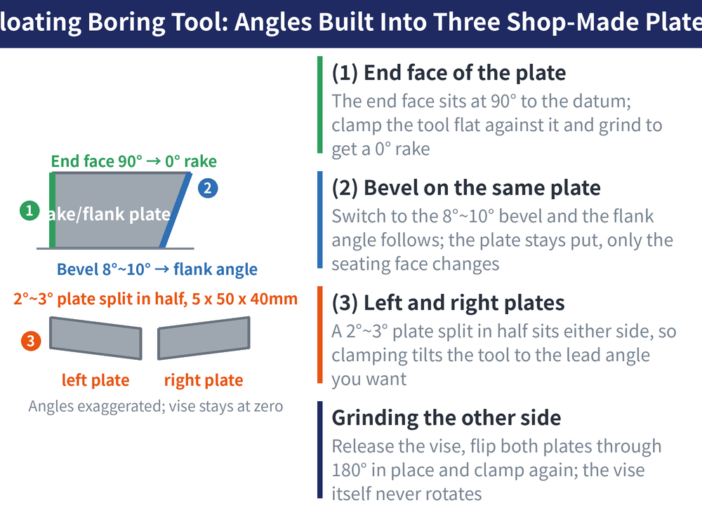
The source's answer is do not turn the vice, change the block. Set the fixed jaw parallel to the machine axis once, then leave the vice alone, and put all the angle arithmetic into the shape of three home-made blocks.
| Home-made part | Form and purpose |
|---|---|
| Rake and clearance block | Two faces: an end face square to the datum for the 0° rake, and an 8°~10° bevel for the primary clearance |
| Left and right side blocks | One 2°~3° angle block sawn in half, 5mm thick, 50mm long, 40mm high, one either side of the first block |
| Machine and wheel | Tool grinder with a precision machine vice and a diamond wheel |
Three steps: put the tool's wide face against the block's end face, clamp and grind for the 0° rake; move it to the bevel and the primary clearance is done; leave that block where it is, add the side blocks either side, rest the tool on the moving jaw's bevel, and on clamping it swings itself to the side angle. Grind one side, release, flip the side blocks 180° in place, clamp and grind the other.
Two figures are reproduced as flagged in the source rather than interpreted: the 8°~10° primary clearance is inferred from the block's own drawing (the text never states the range the block produces), and no figure is given anywhere for the clearance behind the side angles, so none is supplied here.
3. The precision route: the targets first
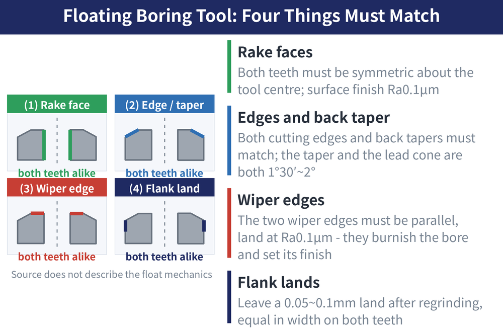
The simple method answers "how do I hit the angle". The precision route answers "how fine does it have to be". With both halves assembled, first grind the two sides square to the seating face (0.02mm) and the seating faces parallel (0.01mm).
| Feature | Requirement |
|---|---|
| Rake face | Ra0.1μm; both teeth symmetrical about the tool centre |
| Sizing burnishing edge | Land at Ra0.1μm; both cutting edges and back tapers symmetrical; the two burnishing edges parallel |
| Flank | Ra0.1μm; leave a 0.05~0.1mm land, the same width on both teeth |
The sizing burnishing edge works the bore wall by pressure, so it sets the hole's finish outright and carries the tightest requirement. Grind its width to 0.4~0.5mm and stop.
4. Two set-ups on one fixture
The burnishing edge and the clearance share a universal tool grinder and one fixture. The only difference is whether an angled shim goes underneath.
| Grinding | Set-up |
|---|---|
| Burnishing edge | Tool straight onto the locating face, no shim; both locating pins the same diameter |
| Setting it true | Indicate the line through both pin centres square to the table's longitudinal feed |
| Its wheel | Resin-bonded diamond cup wheel, grit 200/230#~230/270#, concentration 50%~75% |
| Clearance | Add an angled shim on the locating face, cut to the clearance angle wanted, and clamp the tool against it |
| Its wheel | Green silicon carbide cup wheel, grit 60#~80#, grade J~K; or a diamond cup wheel instead |
The grinding data given for the clearance is 14~18m/s wheel speed, 0.01~0.02mm cross feed per double stroke and 1~1.5m/min longitudinal feed, with the last one or two strokes slower still, about 0.5m/min. These are single-source values; prove them against your own wheel and machine. The flank comes out below Ra0.4μm.
5. Tapers: one sleeve switches the role
To grind the 1°30′~2° cutting taper and back taper, the fixture is the same one used for the clearance, with the same angled shim underneath. The only variable is whether a sleeve goes on the locating pin (outside diameter D, bore equal to the pin diameter d).
| Pin state | What gets ground |
|---|---|
| Bare pin of diameter d | The 1°30′~2° back taper and its clearance |
| Sleeve moved to the other d pin | The cutting taper at an entering angle of 1°30′~2°, and its clearance |
There is also a way round building the fixture: use a grinding boring bar instead — a bar whose square hole matches the real one in size and form, with a threaded hole added on top. Drop the tool in, support the bar on centres, indicate it symmetrical about the bar axis and lock it. That lets you treat the floating tool as a two-tooth reamer and grind the burnishing edge, both tapers and their clearances in one setting. Oil it before storage. For the full reamer routine, see Regrinding a Reamer.
6. Frequently Asked Questions (FAQ)
Q: Simple method or precision route?
It depends on the requirement. The simple method is about hitting angles quickly and repeatably in your own shop; the precision route is about getting every face to Ra0.1μm with both teeth symmetrical, which you take when bore finish is specified. They are not exclusive — grind the angles the simple way, then go precision.
Q: Why is the burnishing edge held to a tighter spec?
Because it is not cutting — it presses and burnishes the bore wall, so it decides the hole's surface finish. Hence Ra0.1μm on the land and both edges parallel. Width is ground to 0.4~0.5mm; wider is not better.
Q: How can one sleeve produce two different tapers?
The sleeve moves where the tool pivots on the fixture. On the bare pin you get the back taper; move the sleeve to the other pin of the same diameter and that pivot shifts, so the same shim now produces a cutting taper at 1°30′~2°. The fixture never changes, only the datum does.
Q: What if there is no dedicated fixture?
Use a boring bar kept for grinding, with its square hole made to the same accuracy as the working bar and a threaded hole on top. Fit the tool, support the bar on centres, indicate it symmetrical and lock it — then grind every face in one setting as if it were a two-tooth reamer.
This article is part of Tool Regrinding: The Complete Guide — Decide Whether to Grind, Then Look Up How, With What, and How to Check; that guide shows how the whole topic fits together.
Published: 2026-08-18|Last updated: 2026-08-18









