
Form Tools Cannot Be Ground by Feel: Build a Jig, or Cut the Tool on Wire EDM
A form tool's edge is not a straight line, and grinding one by feel defeats even an experienced hand. There are two ways out: build a jig so a mechanism replaces the feel, or skip grinding altogether and cut the tool profile on wire EDM. This article compares both on principle, cost and limits, including the two details most often missed on the EDM route — projection distortion and wire offset.
1. Why form tools cannot be ground by feel
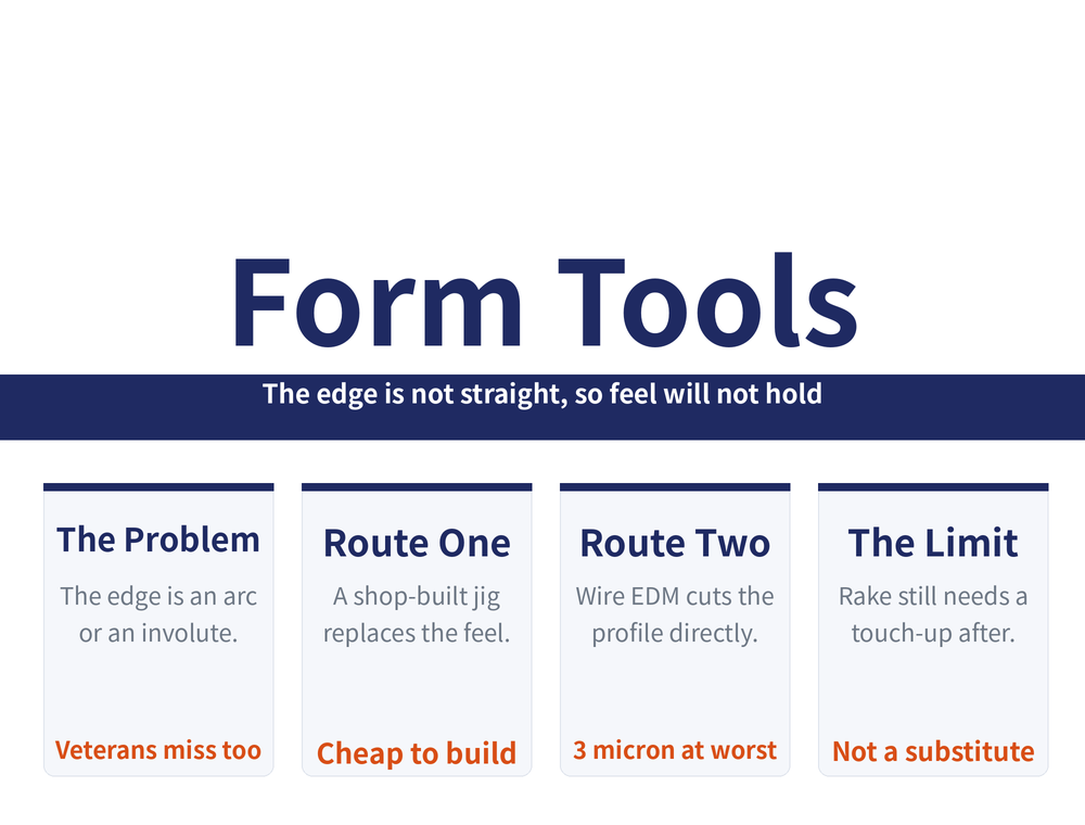
On an ordinary turning tool the edge is straight or a simple cone, and feel is good enough. A form tool is not — the edge of a large-radius template tool is an arc; on a finger gear cutter the working generatrix is an involute and the edge is a helix. Put plainly: these tools have long been ground by hand, and even an experienced hand often fails to hit the requirement.
The problem is not skill. It is that feel cannot reproduce a curve consistently. Both routes therefore point the same way: replace the feel with a mechanism.
2. Route one: build a jig and let the mechanism draw the arc
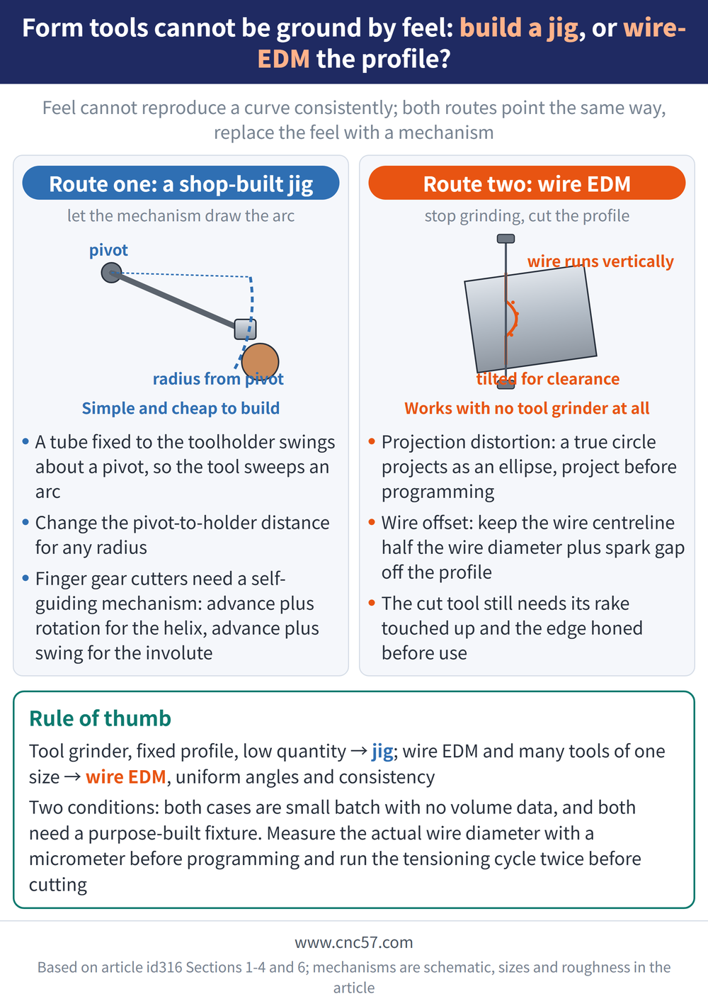
The jig for the large-radius template tool is surprisingly simple: a 3m channel section with one end on the tool grinder and the other on a stand; a 3m seamless tube fixed at one end to the tool holder and clamped at the other in a pivot body it can rotate about. The tool then sweeps an arc across the table plate, and the radius is simply the distance from the pivot axis to the wheel's working face. Change the pivot-to-holder distance and you get any radius you want.
| Grinding | How |
|---|---|
| Rake | Outer edge of a 45° cup wheel dressed to the rake angle; swing tube and holder |
| Clearance | Tilt the wheelhead, grind on the wheel's outer radius; angle and travel set by the clearance |
The jig's measured result: rake face below Ra0.9μm and flank below Ra1.6μm, from a jig it calls simple and cheap to build.
3. The harder case: a self-guiding mechanism for finger gear cutters
A finger gear cutter is not a complete cone, so it cannot be ground by setting a mounting angle — the edge has to travel along the helix and along the generatrix at once. The self-guiding mechanism splits that into two superimposed motions:
Advance plus rotation makes the helix; advance plus swing makes the involute. A tension spring holds the edge against the slot in the guide plate, so as the table advances the slot forces the body to turn and swing together. Where the wheelhead cannot be tilted, the swinging cradle is tilted instead and the slot height becomes h1 = (H−h2)cosα + h2 − r·sinα (⚠ existing derivation; transcribed here without independent checking).
Three constraints: use a cup or bowl wheel so the tool's nose can enter the wheel; the accuracy of the involute depends on how well the tool's outside diameter was ground; and what you get is the normal clearance angle.
4. Route two: stop grinding and cut it on wire EDM
A shop with no tool grinder can only rub a form turning tool on a bench wheel, and accuracy suffers. The second route is to cut the tool profile directly on a wire EDM machine. Four points on the fixture: both faces of the base plate parallel, the upright square to the base's top face, accurate angular graduations, and a re-check of positional error on a surface plate after assembly, especially the zeroing of the angular scale.
Two traps on this route:
| Trap | What to do |
|---|---|
| Projection distortion | The wire runs only vertically, so clearance comes from tilting the shank; a true circle projects as an ellipse — project the geometry to the horizontal plane before programming |
| Wire offset | Keep the wire centreline (d+f)/2 off the projected profile; d is wire diameter, spark gap f is 8μm for HSS and 6μm for carbide |
Two shop details: measure the wire's actual current diameter with a micrometer before programming, and run the tensioning cycle twice before cutting to kill resonance and wander, or the surface picks up streaks. Cutting speed is inversely related to finish — measured trials ran from Ra0.4μm at best to Ra3.2μm at worst.
5. Cutting in batches: seven at a time, measured
The second case wedges blank inserts seven to a set in a 90° indexing fixture, with 2mm spacers between them to suit the rake angle. Taking a spring-clamped HSS parting insert as the example:
| Item | By hand | Wire EDM |
|---|---|---|
| Time | 15–20 min each | 7–10 min each on average |
| Angle consistency | Hard to hold to spec | Uniform to standard |
| Surface finish | Mostly Ra3.2μm with burn marks | Down to Ra0.8μm |
| Tool life | — | 15–20% above hand ground |
Single-source measured values — verify them on your own equipment.
6. The limit: cutting does not remove the grinding
This route is not a cure-all. Note: a form turning tool cut this way still needs its rake and secondary rake touched up before use, for chip flow and edge strength, and the batch-cut inserts still need edge honing. For honing see Edge Preparation After Regrinding.
Two conditions to read carefully: both cases are small batch (seven to a set) and there is no data for volume production; and both need a purpose-built fixture and existing equipment. The same approach suits carbide stainless chipbreaker tools, worm thread tools, trapezoidal thread tools and internal or external radius tools.
7. Frequently Asked Questions (FAQ)
Q: Which route should I take?
It depends on your equipment and on how many of the same tool you need. With a tool grinder, a fixed profile and low quantities, the shop-built jig wins — cheap, and what comes off it is finished. With a wire EDM machine and many tools of one size, EDM wins on consistency: by hand every tool differs, cut they are uniform to standard.
Q: Why does a true circle come out as an ellipse?
Because the wire on a two-axis machine only travels vertically, so the tool's clearance is produced by deliberately tilting the shank in the horizontal plane. Tilt the shank and the tool's plane geometry distorts when projected onto the horizontal, turning a circle into an ellipse. So you cannot program from the original points, lines and arcs — project them at the tilt angle first, then calculate.
Q: Why is the offset (d+f)/2?
Because the wire has a diameter d and the discharge leaves a gap f between wire and workpiece; the two together are the full kerf width, and half of that is how far the wire centreline should sit off the profile. The gap f varies with tool material: 8μm for high speed steel, 6μm for carbide. Measure the wire's actual diameter rather than using the nominal figure.
Q: How accurate is a cut tool?
Measured records show form turning tools cut this way match the design data, with individual dimensional error of only 3μm at worst. Surface finish is inversely related to cutting speed, from Ra0.4μm at best to Ra3.2μm at worst — slow down for a better surface. Single-source measured values.
This article is part of Tool Regrinding: The Complete Guide — Decide Whether to Grind, Then Look Up How, With What, and How to Check; that guide shows how the whole topic fits together.
Published: 2026-08-18|Last updated: 2026-08-18









