
Hydraulic Fixture Valves and Plumbing: Poppet Valves, Sequence Valves, Coupling and Auto-Disconnect
When a hydraulic fixture disappoints, the cylinder is rarely the problem — the valves and the plumbing are. Whether the directional valve leaks internally, how several cylinders are sequenced, whether the power unit stays permanently connected or disconnects, and whether oil runs through external steel tube or through a manifold plate: these decide whether the system overheats, whether it can run unattended, and how serviceable it will be. This guide covers poppet valves, sequence valves, check valves and pressure switches, then coupling methods, plumbing types and pipe threads.
1. Directional Valves: Only a Poppet Type Will Do
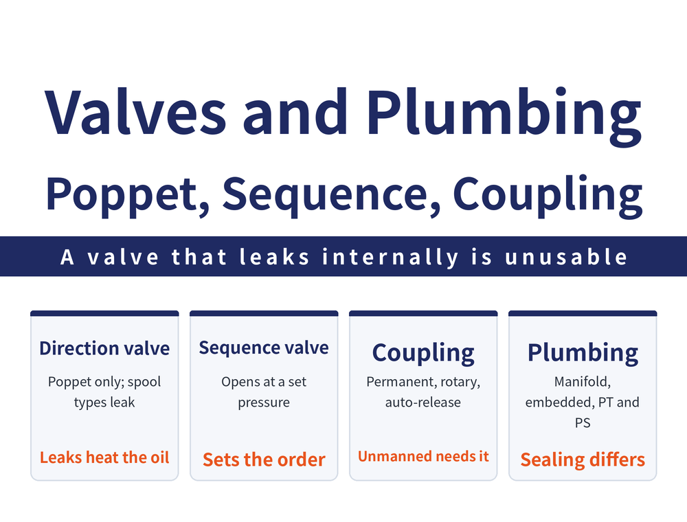
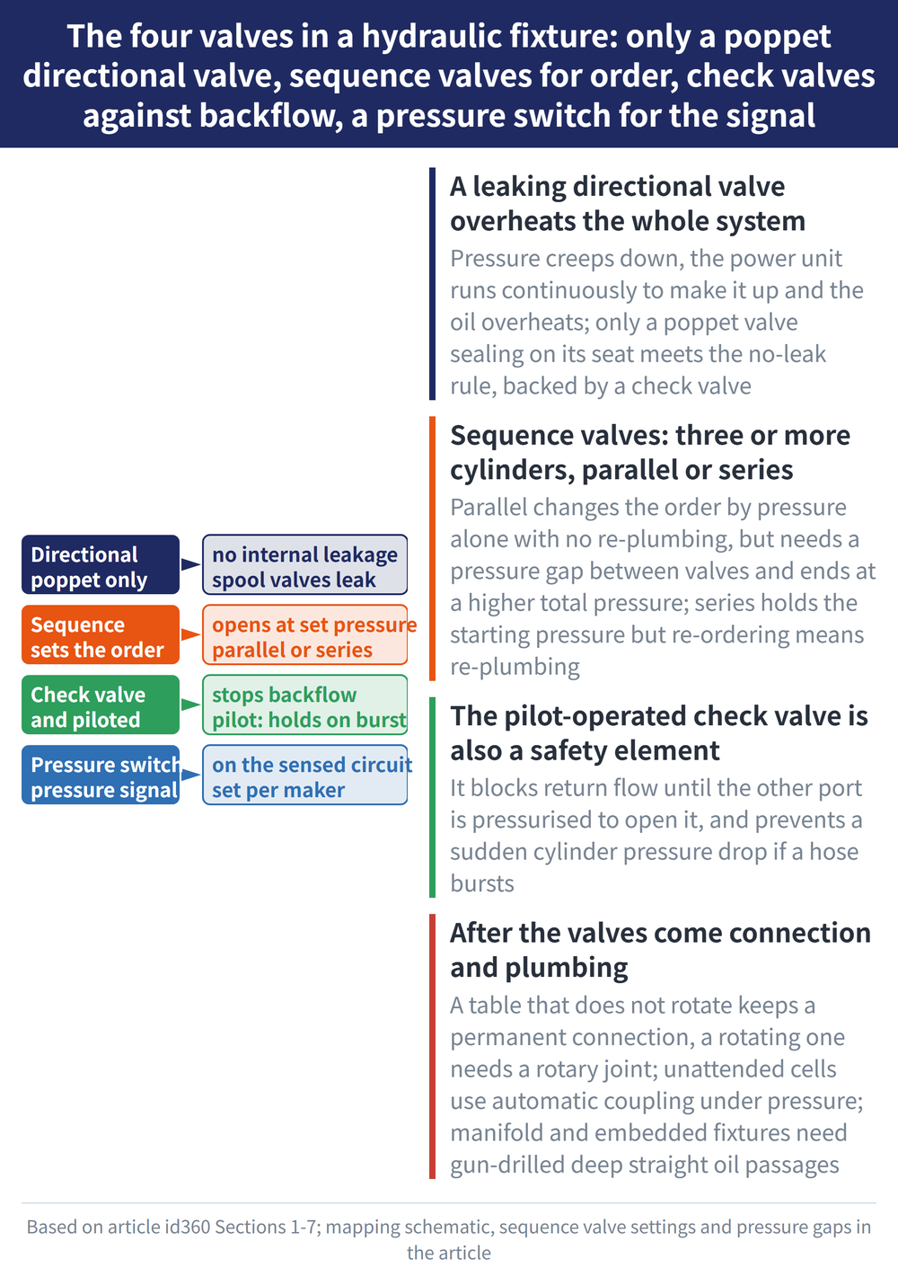
A directional valve on a hydraulic fixture has one hard requirement: no internal leakage at all. If the valve leaks internally, pressure bleeds away, the power unit has to keep running to top it up, and the hydraulic oil overheats.
Only a poppet valve (a poppet seated against a seat face) meets that requirement; spool-type directional valves leak internally and are not suitable for hydraulic fixtures. Used with a directional valve, a check valve is still needed to prevent leakage. For how the hydraulic system and its power sources are put together, see Hydraulic Workholding Basics.
2. Sequence Valves: Making Cylinders Act in Order
A sequence valve has one job: to separate the order in which several cylinders act. The principle is simple — while the inlet Pp port is below the set pressure, the outlet Pa is 0; once Pp reaches the set pressure, the valve opens and Pa equals Pp.
Example from the source: cylinder 1 acts first, the sequence valve opens when pressure reaches 30 bar, and cylinders 2 and 3 then act. That figure is transcribed from one specific scenario in the source, not a general threshold — the actual setting follows from the clamping force required.
3. Three or More Cylinders: Parallel or Series
Once enough cylinders are involved to need several sequence valves, they can be connected in parallel or in series:
| Item | Parallel | Series |
|---|---|---|
| Connection | All P ports joined | Next P port fed from previous A port |
| Pressure setting | Each valve set differently | May be set the same |
| Changing the order | Change pressure only, plumbing untouched | Plumbing must be changed |
| Total pressure once complete | Higher | Stays at the starting pressure |
Parallel connection carries one explicit requirement: the pressure difference between sequence valves must be at least 25 bar (or 50 bar) for the actions to separate. The source lists both figures side by side without choosing one, and this article transcribes them as given rather than narrowing them.
4. Check Valves, Pilot-Operated Check Valves and Pressure Switches
A check valve prevents pressure loss or reverse flow in the circuit, which is what covers the leakage requirement of the poppet directional valve above.
A pilot-operated check valve adds a layer of control: it blocks reverse flow normally, and when the oil does need to return, pilot oil at the other end opens it so the cylinder oil goes back to the tank. It also acts as a safety element — it prevents a sudden pressure drop in the cylinder if a hose bursts.
A pressure switch goes into circuits that need pressure detection, as the sensing element for the pressure signal. The source gives no trigger pressure and no specification figures, so take those from the manufacturer's datasheet.
5. Connecting the Power Unit: Permanent and Rotary
Connection falls into two classes. In a permanent connection the hose stays connected to the power unit at all times, which is the safest to use; a disconnect-type connection is joined only when the part is changed.
| Type | Where it is used |
|---|---|
| Permanent (general machine tool) | Any single-table machine |
| Permanent (pallet changer) | One hose per assigned pallet, pallet does not rotate |
| Rotary coupling (single line) | Indexing heads or a rotary table with one fixture |
| Rotary coupling (multi-channel) | Channels controlled separately, single or double acting |
The test is simple: as long as the table does not rotate, a permanent connection still works even with an automatic pallet changer; only special-purpose machines with a rotating table have to move to a rotary coupling or rotary valve. The source's rotary valve example is a six-station single-acting circuit: one station loads and unloads while the other five stay clamped, which saves fitting every station with its own operating circuit.
A fully independent circuit can add an accumulator, which stores hydraulic energy using pre-charged nitrogen to reduce pressure variation caused by temperature and to compensate for internal leakage in the circuit.
6. Disconnect Systems: Manual and Automatic Coupling
Disconnect-type connection is used where there is an automatic pallet changer, a flexible manufacturing system (FMS) or a flexible manufacturing cell (FMC). A single-acting circuit can use manual coupling and uncoupling directly.
Manual coupling on a double-acting circuit suits an FMS with long clamping times — the longer the part stays clamped, the less often coupling happens, so the efficiency loss of doing it by hand is acceptable.
Going further means an automatic coupling and uncoupling system, used for FMS/FMC and for two or more automatic pallet changers. The machine side carries an automatic coupling unit, the pallet side a coupling nipple unit, with inductive position control to confirm the coupling is seated before oil is admitted; the system is single-acting or double-acting to match the circuit.
One difference from the manual method matters most: the automatic system couples and uncouples hydraulically and can do so under pressure, which is what makes unattended operation possible.
7. Plumbing Inside the Fixture: Four Types and Gun Drilling
Plumbing inside the fixture comes in four types, differing in where the oil runs:
| Type | Oil path |
|---|---|
| A Standard tube | Fittings and steel tube link fixture and elements |
| B Standard tube, double-plate fixture | Tubing runs inside a double base plate |
| C Manifold plate | Oil galleries machined into the base plate |
| D Embedded elements | Hydraulic elements set into the fixture body |
The source notes that standard tubing becomes hard to service once the runs get complex, and that manifold-plate and embedded designs were developed to solve exactly that. Embedded elements give a clean fixture with no exposed plumbing, at a higher machining cost, because the oil galleries have to be cut inside the fixture body.
That leads to one required process: gun drilling is the necessary machining method for manifold-plate and embedded fixtures, whose oil holes must be deep and straight beyond what ordinary drilling achieves. After drilling, deburr and clean the holes carefully; burrs or debris left inside affect the sealing and the action of the hydraulic elements.
8. Pipe Threads: PT and PS Differ in How They Seal
There are two pipe thread types, and the difference is the sealing principle, not which one is better:
| Type | Sealing method | Auxiliary material |
|---|---|---|
| Tapered pipe thread (PT) | The thread itself is tapered and seals on the thread | Needs tape seal or sealing adhesive |
| Straight pipe thread (PS) | Seals on a metal contact face and an edge | None required |
The source explains only the difference in sealing principle and gives no thread dimensions at all (no pitch, no threads per inch, no tolerances), and cites no standard number, so this article does not fill them in. In practice, remember the direction only: PT always needs tape or sealant, while PS seals on its edge and should not be wrapped. Take dimensions, tolerances and mating pairs from the pipe thread standard or the supplier specification.
9. Assembling a Steel Tube Fitting
With a steel tube fitting (rather than a thread screwed straight in), the wrong order means no seal:
| Step | Action |
|---|---|
| 1 | Slide the nut onto the tube, then the ferrule |
| 2 | Push the tube fully home and tighten the nut |
| 3 | The ferrule bites into the tube, sealing and gripping it |
Once the run is complete, clamp the tube in place and bend it with a tube bender. How much clamping force the part itself should get, and where it should be applied, is a separate question — see Why Vise Clamping Distorts the Workpiece.
10. Frequently Asked Questions (FAQ)
Q: Can a hydraulic fixture use an ordinary spool directional valve?
No. The directional valve must have no internal leakage, or the power unit runs constantly to top up pressure and the oil overheats. Only a poppet valve meets that requirement; spool types leak internally. A check valve is still fitted alongside to prevent leakage.
Q: Should several sequence valves be parallel or series connected?
It depends on whether you change the order often or care about final pressure. Parallel lets you re-order by changing pressures alone, but the valves need at least 25 bar (or 50 bar) between settings and total pressure ends higher; series needs no pressure difference and stays at the starting pressure, but re-ordering means re-plumbing.
Q: Which connection method suits unattended operation?
An automatic coupling and uncoupling system. It couples hydraulically and can do so under pressure, with inductive position control confirming the coupling is seated before oil is admitted, which suits FMS/FMC and two or more automatic pallet changers. Where the table does not rotate, a permanent connection still applies.
Q: Do PT and PS pipe threads need thread seal tape?
A tapered PT thread seals on the thread and needs tape seal or sealing adhesive when tightened; a straight PS thread seals on a metal contact face and an edge and needs nothing else. The source gives no thread dimensions, so take actual sizes and mating pairs from the pipe thread standard or the supplier specification.
This article is part of Workholding and Fixtures: The Complete Guide - Locate First, Then Clamp; How Much Force and Where It Comes From; that guide shows how the whole topic fits together.









