
Pneumatic Clamping Math: Force Formula, Three Actions, Air System
Pneumatic clamping comes down to one equation: P = F / A. What trips people up is the units — the worked example substitutes a 50 mm bore as "5", which is centimetres. This guide sets out the thrust formula and that unit trap first, then covers the three clamping actions, the compressed air system and the cylinder types.
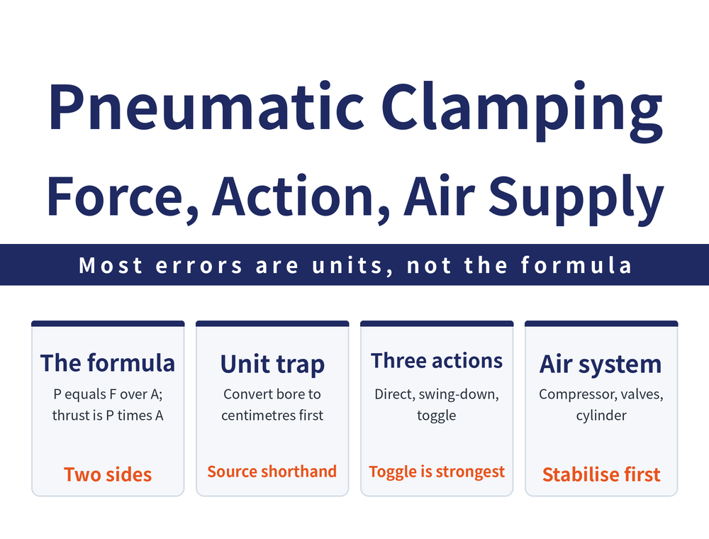
1. Start With the Formula: P = F / A
Pneumatic clamping force comes from compressed air pushing a piston. Pressure, force and area relate through a single equation:
P = F / A (F: force in newtons, N; A: area in square centimetres, cm²)
Turned around, it gives you the selection figure: thrust F = P × A. Bore sets A, the pressure regulator sets P, and their product is what the cylinder can deliver. The conversions below are quoted as given:
| Quantity | Conversion value |
|---|---|
| Force | 1 kgf = 9.8 N |
| Pressure | 1 bar = 10 N/cm² ≈ 1.03 kgf/cm² |
These conversion values are approximate by design, reproduced here without recalculation or correction.
2. The Worked Example: Why 50 mm Bore at 5 bar Gives About 98 kgf
Read the numbers together with their premises: cylinder bore dk = 50 mm, operating pressure 5 bar.
Thrust F = P × A = P × (dk² × π/4) = 5 × (5² × 3.14/4) ≈ 98 kgf
🔴 The unit trap: dk enters the formula as "5", not 50 — the unit is centimetres (5 cm = 50 mm). That is the worked example's own unit conversion logic, not arithmetic added here. When applying this formula, convert the bore to centimetres first; feeding millimetres straight in throws the result out badly.
The operating pressure of 5 bar is likewise substituted as the bare number "5", effectively treating it as 5 kgf/cm², which follows the 1 bar ≈ 1.03 kgf/cm² conversion above. This is the worked example's simplified notation and is not corrected here. The 98 kgf holds only under those premises — it is not a general specification, and a different bore or pressure means a fresh calculation.
3. Three Clamping Actions: Direct, Swing, Toggle
Pneumatic clamps are classified by how the piston force reaches the part:
| Type | Action | Feature |
|---|---|---|
| Direct-acting clamping cylinder | Piston thrust clamps the part directly | |
| Swing (turn-and-press) clamping cylinder | As the cylinder strokes down it swings the clamp arm through an angle, usually 90 degrees, onto the part | Easier part loading and unloading |
| Toggle clamping cylinder | The cylinder drives a toggle linkage | Produces greater clamping force |
The thrust from section 1 corresponds to the direct-acting path. With a swing or toggle unit the force passes through a linkage first, so take the delivered clamping force from the component maker's specification.
4. Air Compresses, Which Is Why Toggles Exist
The medium is the real difference between air and hydraulics: air is compressible. With a clamp that simply presses down on the part, a cutting force acting against the clamping direction and exceeding the clamping force will push the clamp arm open.
That is the reason for the toggle joint design: it produces a greater locking force and keeps the clamp arm from being pushed open. Pneumatic quick clamps mostly take this route.
5. Building the Air System: Compressor and Control Elements
Compressed air comes from an air compressor, and three types are common:
| Type | Principle and current use |
|---|---|
| Reciprocating piston compressor | A piston reciprocating in a cylinder draws in and compresses air; the most widely used type, multi-stage designs reach fairly high pressure, and market models output around 7 bar (approximate figure) |
| Sliding vane compressor | Sliding vanes on a rotating rotor draw in and compress air; can be built in multiple stages for higher pressure |
| Screw compressor | A male and female screw pair forms chambers that expel compressed air as they turn; now fairly widespread |
Map that 7 bar back onto the formula in section 1: pressure is the variable you set, so whatever the regulator is dialled to is what the thrust becomes. The control elements a system needs:
| Control element | Function |
|---|---|
| Three-point unit | Water draining, pressure regulation and lubrication |
| Directional control valve | Manual and solenoid types |
| Pressure reducing valve | Adjusts pressure |
| Flow control valve | Adjusts flow to control speed |
6. Cylinders and Rotary Cylinders: Single- and Double-Acting
Cylinder construction splits into two, and the difference is what drives the return stroke:
| Type | Extend | Return |
|---|---|---|
| Single-acting cylinder | Supply compressed air and the piston extends | Spring return; with no air supplied the piston sits at home position |
| Double-acting cylinder | Air to port A and the piston extends | Air to port B and the piston returns to home position |
There is also the pneumatic rotary cylinder: as the piston strokes down it rotates the piston rod 90 degrees to clamp the part, and releasing clears the way for loading — the same loading logic as the swing clamp in section 3.
7. How Directional Control Valves Are Classified
The valve decides where the air goes, and its designation reads as ports and positions — ports are connections, positions are switching states:
| Valve | Configuration and use |
|---|---|
| 2-port, 2-position valve | Simply shuts off the connection between the air supply and the pneumatic component |
| 5-port, 2-position valve | Port 1 air supply inlet, port 2 cylinder inlet A, ports 3 and 5 exhaust, port 4 cylinder inlet B; actuation is either manual with manual return, or solenoid with spring return |
| 4-port, 3-position manual valve | BA/EX/PR configuration, connected to cylinder ports A and B, with R as exhaust |
8. When to Move From Manual to Pneumatic
Clamping force can be generated by five physical effects, and air and hydraulics both sit under "fluid pressure converted into clamping force", that is Pascal's principle, capable of producing large clamping forces. The conclusion: hydraulics and pneumatics are the principles best suited to automated clamping, though manual clamping remains very widely used.
Put another way, going pneumatic does not buy more force — it buys repeatable force. The same cylinder at the same regulator setting clamps identically every cycle, with no operator-to-operator variation. If your current problem is parts measuring out of spec after release, read Why Vise Clamping Distorts the Workpiece first to establish whether the cause is force magnitude or clamp point, then decide whether to change the power source.
9. Frequently Asked Questions (FAQ)
Q: How much thrust does a 50 mm bore cylinder at 5 bar deliver?
The worked example arrives at about 98 kgf under those premises, using F = P × (dk² × π/4). That figure is the worked example's arithmetic for its stated conditions, not a general specification; a different bore or operating pressure requires a fresh calculation.
Q: Why does the formula substitute dk as 5 rather than 50?
Because the worked example is set up in centimetres, and 5 cm is 50 mm. That is the worked example's own unit conversion logic, reproduced here without correction; when you apply the formula, convert the bore to centimetres before substituting it.
Q: Why do pneumatic clamps so often use a toggle?
Because air is compressible. With a clamp pressing directly on the part, a cutting force opposing the clamping direction and larger than the clamping force pushes the arm open; a toggle joint produces a greater locking force and keeps the arm closed.
Q: What pressure does a shop air supply usually run at?
Market reciprocating piston compressors output around 7 bar, described as an approximation rather than a precise specification. Take the usable pressure from your own compressor and regulator settings.
This article is part of Workholding and Fixtures: The Complete Guide - Locate First, Then Clamp; How Much Force and Where It Comes From; that guide shows how the whole topic fits together.









