
A pull stud is the critical part that lets the spindle's internal drawbar mechanism pull a tool holder tight once it's seated - its type and spec must exactly match the spindle's drawbar system, since a mismatch means insufficient clamping force, which is genuinely dangerous. This guide explains how pull studs work, how they're classified by standard, and what to confirm before selecting one.
1. What a Pull Stud Actually Does: Pulling the Holder Truly Tight
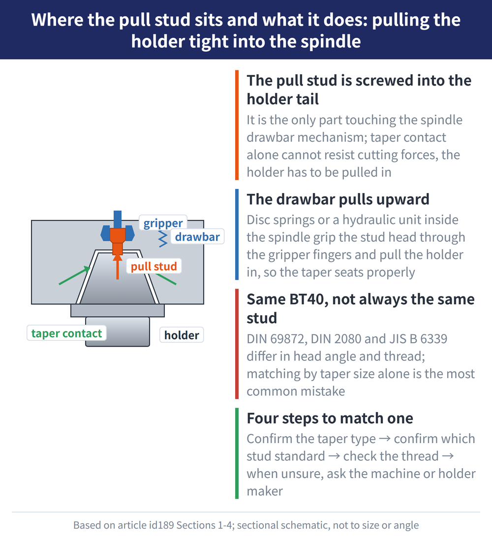
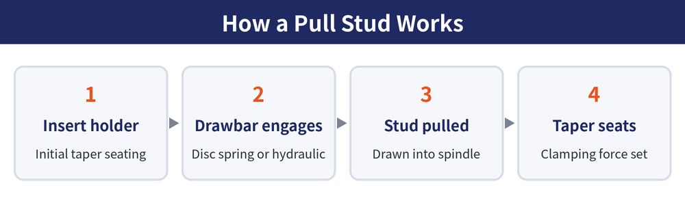
Once a tool holder is inserted into the spindle taper bore, taper contact alone isn't enough to withstand the axial and radial forces of cutting. The spindle's internal drawbar mechanism (typically a disc-spring or hydraulic system) needs to pull the holder further into the spindle via the pull stud so the taper surfaces seat fully and generate adequate clamping force. The pull stud is threaded into the rear of the holder and is the sole contact part between the holder and the spindle's drawbar mechanism - if the pull stud's type or thread spec doesn't match the spindle's gripper, the result ranges from reduced clamping force and lower precision to, in a worst case, the holder coming loose during rotation. It's one of the safety-critical parts on a machine, so selecting one carefully matters.
2. Pull Studs Classified by Spindle Taper Standard
Different spindle taper systems (see Spindle Taper Systems Overview) pair with different pull stud specifications. Common classification standards include:
| Standard | Taper System | Notes |
|---|---|---|
| DIN 69872 | 7:24 steep taper family (BT/ISO/SK, etc.) | One of the common European pull stud standards |
| DIN 2080 | 7:24 steep taper family | Another common European pull stud standard, with a slightly different form from DIN 69872 |
| JIS B 6339 (MAS-BT) | BT series | Japanese standard; BT30/40/50 pull studs follow this spec |
Two holders both labeled "BT40" may still use pull studs from different standards (e.g. a DIN system versus a JIS system), and their thread specs and pull-stud angles may not fully match. Always defer to the spindle drawbar mechanism's OEM specification - don't select a pull stud based on the taper designation alone. This is the single most common mistake in pull stud selection.
3. Common Differences Between Pull Stud Types
| Item | Notes |
|---|---|
| Thread specification | Varies with taper size (e.g. BT30/40/50) and governing standard; must match the spindle gripper's clamping stroke |
| Pull stud angle / form | Head angle and gripping groove design differ by standard, affecting how it engages the gripper |
| High-speed spindle compatibility | Some high-speed spindles have additional requirements for pull stud balance and strength - confirm this during selection |
Specific thread dimensions, length, and angle values for pull studs vary by taper size and standard version, so always confirm against the machine's OEM manual or the tool holder catalog's stated specification rather than matching by appearance or taper designation alone - even where the taper designation is the same, pull studs across different standard families (e.g. DIN vs. JIS) may not be interchangeable.
BT vs HSK in detail: see BT vs HSK Spindle Taper Comparison.
4. Steps to Confirm the Right Pull Stud
| Step | Notes |
|---|---|
| Confirm the spindle taper type | First identify whether the machine is BT, ISO, SK, HSK, etc. (see the Spindle Taper Systems Overview) |
| Confirm the pull stud's governing standard | The same taper designation may pair with different pull stud standards (DIN 69872 vs. DIN 2080 vs. JIS) - check the machine's OEM specification |
| Verify the thread specification | Confirm the pull stud thread matches the threaded hole at the holder's rear |
| Consult the manufacturer if uncertain | Contacting the machine or tool holder supplier directly is the fastest, safest way to resolve any doubt |
Holder care and life: see Tool Holder Maintenance Guide.
FAQ
Q1: What happens if the wrong pull stud is installed?
A mismatched pull stud type or thread spec can range from reduced clamping force and lower machining accuracy (increased runout) to, in a severe case, the holder coming loose during high-speed rotation. This is a safety-critical part for both the machine and the operator, so always verify the specification carefully and confirm with the manufacturer if in doubt rather than guessing from experience.
Q2: If two holders are both BT40, are their pull studs interchangeable?
Not necessarily. Both may be labeled BT40 but follow different pull stud standards (e.g. DIN 69872, DIN 2080, or JIS B 6339), and the angle and thread specs across these standards may not fully match. Even if they look similar, correct engagement with the spindle gripper isn't guaranteed - always go by the pull stud spec stated by the machine manufacturer.
Q3: How often should a pull stud be replaced?
There's no fixed industry-wide replacement interval. It's best to periodically inspect the pull stud visually for deformation, thread wear, or cracks, and replace it immediately if anything looks off. High-speed spindle applications, which have tighter balance and strength requirements, warrant more frequent inspection - refer to the machine's OEM maintenance manual for a specific schedule.
Q4: Do HSK holders need a pull stud too?
HSK's clamping mechanism works differently from the separate threaded pull stud used in the traditional 7:24 steep taper family (BT/ISO/SK, etc.). The HSK holder's shank itself is designed to be gripped and drawn in directly by the spindle's internal clamping mechanism, so it doesn't use a conventional add-on pull stud part - refer to the specific HSK system's OEM specification for the actual mechanism.









