
Blind Bores, Keyways and Thin Sleeves: Internal Grinding Countermeasures
Most internal grinding rules assume a clean through bore. What actually arrives is often blind, stepped, broken by a keyway or a cross hole, or the whole part is a thin sleeve. These forms produce defects a through bore never shows, and almost none of the answers live in the grinding parameters - they are changes to work holding, to how the wheel contacts the bore, and to the order of operations. This article covers the four cases and how to measure the result.
1. Blind and stepped bores: four points
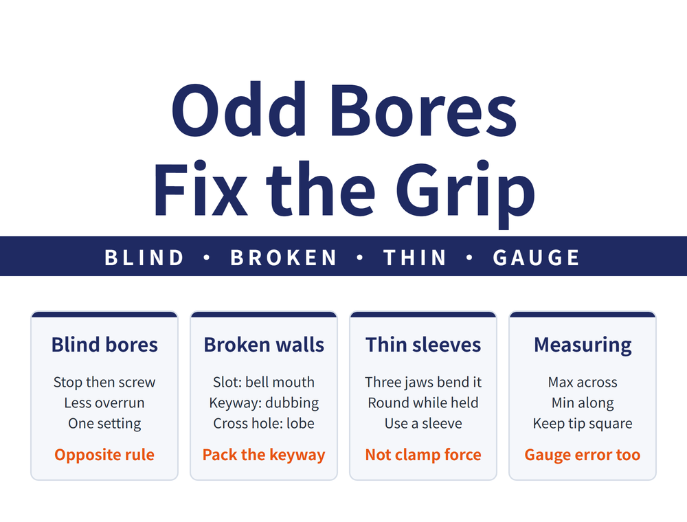
The danger in a blind bore is the wheel face hitting the bottom, so the stroke is set twice: rough it in on the left stop, then fine tune with the screw on that stop so the wheel face just enters the relief groove and reverses. Before that, mark the quill from the bore depth and dry run the stroke with neither wheel nor part turning.
| Point | What to do |
|---|---|
| Avoid hitting the bottom | Stop for rough set, screw for fine set, dry run first |
| Avoid forward taper | Short strokes near the bottom; smaller overrun at the mouth |
| Clear swarf | Clean the bore often for wheel life and finish |
| Stepped bore concentricity | Grind every bore in one setting; change quills, not setups |
🔴 Note the overrun goes the other way from a through bore: a through bore takes one third to one half of wheel width, a blind bore takes less at the mouth. Where the bore face has a squareness requirement, use a cup wheel and keep its diameter modest so contact on that face stays one sided. For the through bore rules, see Why Internal Grinding Is the Hardest: Get the Wheel and the Quill Right First.
2. Interrupted bores: three forms, three defects
When a wide slot, a keyway or a cross hole breaks the bore wall, wheel contact is interrupted and form error follows easily. The three forms fail in different ways and take different answers:
| Bore form | Produces | Countermeasure |
|---|---|---|
| Wide slot | Bell mouth each side of the slot | Thicker quill, wider wheel, dress promptly |
| Keyway | Dubbed keyway edges | Larger wheel, narrower, stiffer quill |
| Cross hole | Polygonal bore wall | Larger wheel, stiffer quill material |
For dubbed keyway edges there is a far more direct method: where accuracy matters, pack the keyway with hardwood or a phenolic before grinding.
It does not adjust a parameter, it fills the interruption back into a continuous surface. That is the root answer; parameters only reduce the symptom.
One thing is common to all three: at finish, reduce depth of cut and add spark out passes.
3. Plunge grinding: short bores only, four things to watch
Plunge grinding is productive but only suits parts whose bore is not long. The wheel feeds in continuously under heavy load, so it loads and dulls quickly:
| Item | What to do |
|---|---|
| Wheel | Dress promptly; use a slow infeed at finish |
| Alignment | Spindle or headstock axis parallel to table travel |
| Finish | Spark out with slight manual traverse oscillation |
| Internal face grinding | Wheel diameter under 30mm, or flatness suffers |
Poor alignment is easy to recognise: the internal face comes out convex or concave. Where two bores share a concentricity requirement, for example 40mm and 20mm, grind both in one setting and change quills rather than resetting the part.
4. Thin sleeves: round while held, not round once released
A thin sleeve is the classic part you only discover is wrong at the inspection bench. Clamping force, grinding force, grinding heat and residual stress all distort it, and the most deceptive of them is the three jaw chuck:
The part is held with elastic distortion already in it, so the bore really is round when ground; but the moment the jaws release, that distortion springs back and the bore becomes a curved triangle.
The problem is not that it was clamped too hard. It is that the force arrives at three points.
5. Expanding sleeve or axial clamping: two directions
| Countermeasure | How | What it solves |
|---|---|---|
| Cast iron expanding sleeve | Wall about twice the part wall, one axial slit | Turns three points into a face |
| Axial clamping | Dedicated fixture, nut pressing on the end face | Avoids radial clamping entirely |
Three more things belong with it: separate roughing from finishing so roughing distortion is corrected at finish, use the lowest clamping force and ample coolant at finish, and choose a wheel that is coarser and softer, since a wheel that will not self sharpen raises grinding force and pushes the part out of shape. Where stock removal is large, slacken the jaws slightly and re-clamp gently before the finish pass so the part returns to shape. Heat treatment before and after roughing relieves stress. A part whose end faces are lapped and flat also responds better to axial clamping.
Thin plates are a different subject - thermal and clamping distortion must be treated separately - see Thin Parts Bow After Grinding: Separate Thermal Distortion from Clamping Distortion.
6. Coolant: cast iron bores usually go dry
This one runs against the usual assumption and is worth remembering on its own. Coolant helps temperature, distortion and burn, but a bore clears chips badly, and fluid turns swarf into a paste that loads the wheel face and scores the wall.
Grinding the bore of a brittle material such as cast iron is normally done without coolant.
If a customer insists on flooding a cast iron bore, the scoring they are complaining about may be exactly that - ask what the material is before discussing flow rate.
For other materials it depends on material behaviour, accuracy requirement, bore form and size, and what the machine is set up with. There is no blanket answer.
7. Measuring a bore is easier to get wrong than an OD
| Gauge | Use and key point |
|---|---|
| Plug gauge (go / no go) | Batch work; enter it square and gently, never tap or rock |
| Inside micrometer | Above 50mm; no force device, so zero it before use |
| Bore gauge with indicator | Comparative method for size and roundness; set to a standard |
| Three point bore micrometer | Self centring, constant force; rock it and take the minimum |
The general rule for bore size: find the maximum across the diameter and the minimum along the axis, and the real size is where those two agree. For roundness and cylindricity, read three or four positions around the bore and several along the axis, then compare.
⚠ In a bore you cannot see the angle at which the gauge touches the wall, unlike an outside diameter. An indicator tip must be perpendicular to the surface; with a lever type indicator, the smaller the stylus angle the smaller the error. The error you measured may be one you created, not a fault in the part. For concentricity between bore and outside diameter, mount on a mandrel between centres and read radial run-out, then halve the reading.
8. Frequently Asked Questions (FAQ)
Q: My thin sleeve distorts as soon as I release it. Am I clamping too hard?
Clamping force is only part of it. The root cause is that a three jaw chuck applies force at three points, so the part is held distorted, the bore is genuinely round while ground, and it springs into a curved triangle on release. Identify the current holding method first, then choose: an expanding sleeve to turn three points into a face, or axial clamping to avoid radial force entirely.
Q: The keyway edges dub over. What parameters fix that?
Parameters only reduce it. A larger and narrower wheel and a stiffer quill all help, and at finish you reduce depth of cut and add spark out passes. But the root answer is not a parameter: where accuracy matters, pack the keyway with hardwood or a phenolic so the interrupted surface becomes continuous, then grind.
Q: Should I flood a cast iron bore with coolant?
Normally not. A bore already clears chips badly, and coolant turns the swarf into a paste that loads the wheel face and scores the wall. For other materials it depends on material behaviour, accuracy requirement, bore form and size, and the machine setup, so there is no blanket answer.
Q: Roundness failed on inspection. Is the part definitely bad?
Not necessarily. You cannot see the contact angle inside a bore, so an indicator tip that is not perpendicular, or a lever indicator at too large a stylus angle, will produce error of its own. Remember also to find the maximum across the diameter and the minimum along the axis; the real size is where those two agree.
To trace a defect back to its cause, see Grinding Defects: Tracing Chatter, Burn, Cracks and Size Errors. For internal grinding work holding, motions and parameters, see Cylindrical, Internal and Surface Grinding: Workholding, Motions and Grinding Data.
This article is part of Grinding Wheels and Machines: The Complete Guide - Reading the Wheel, Mounting It, Dressing It, and Tracing Defects; that guide shows how the whole topic fits together.
Published: 2026-09-19|Last updated: 2026-10-24









