
How to Use a Lathe Chuck: Soft Jaws vs Hard Jaws, Hydraulic Chucks and Expanding Fixtures
The same bar held in hard jaws and in soft jaws does not run the same. This guide splits the lathe chuck into four topics: the basic three-jaw and four-jaw chuck, the difference in use between hard and soft jaws, the hydraulic chuck used on CNC lathes, and the expanding fixture that grips through a taper — then returns to how much clamping force you actually need, and closes with the three ways precision clamping mechanisms are driven and the trade-offs in stroke, accuracy and centrifugal force.
1. The Most Basic Way to Hold a Round Part: Three-Jaw and Four-Jaw Chucks
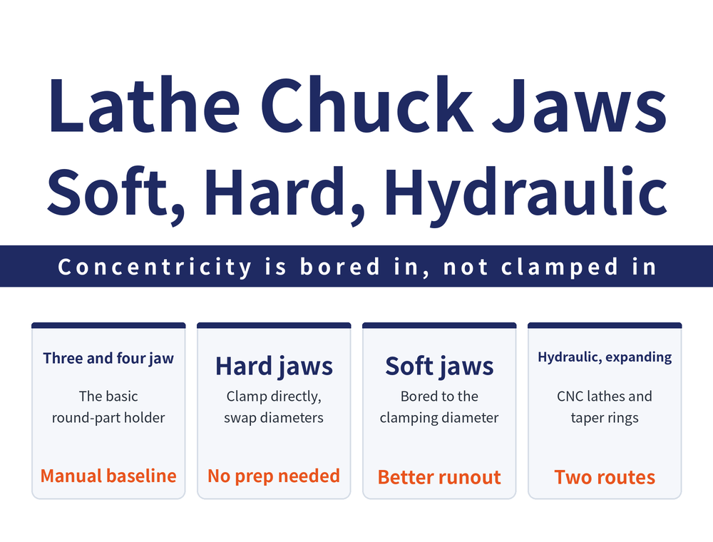
The most basic way to hold a round workpiece is the three-jaw or four-jaw chuck on the lathe. Everything that follows — soft jaws, hydraulic chucks, expanding fixtures — either changes the jaws or changes where the clamping force comes from.
There is no reliable account of how the two types differ in centring action or typical application, so this article does not infer it. To choose between three and four jaws, work from the chuck supplier's specification.
Two situations have their own guides on this site. The four jaws of a four-jaw chuck adjust independently, which is what eccentric turning relies on — see Eccentric Turning: Two Workholding Methods and Three Ways to Check the Offset. A thin-walled part gripped directly in a plain three-jaw chuck is easily distorted — for other ways to hold it and how to sequence the cuts, see How to Sequence Thin-Wall Turning: Roughing, Semi-Finishing, Finishing and Four Countermeasures Against Distortion.
2. Hard Jaws vs Soft Jaws: A Difference in Procedure and in Concentricity
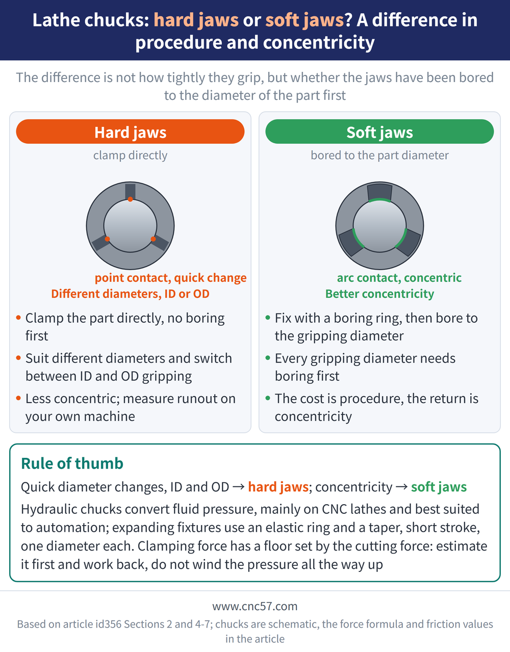
When a lathe chuck holds a round part, a manual chuck can run hard jaws or soft jaws. The difference is not how tightly they grip; it is whether the jaws have been bored to the diameter of the part first.
| Jaw type | Procedure | Clamping concentricity |
|---|---|---|
| Hard jaws | Clamp the part directly; suit different diameters and can switch between ID and OD gripping | Stated only relative to soft jaws; no figure available |
| Soft jaws | Must be fixed with a soft-jaw boring ring first, then bored to the gripping diameter before use | Better |
In short, hard jaws win on changing diameter quickly and gripping either ID or OD; soft jaws win on concentricity, at the cost of one boring operation for every gripping diameter.
3. Why Are Hard Jaws Less Concentric? The Mechanism Is Left Open
This section contrasts only the procedure and the concentricity outcome; the mechanism behind the lower concentricity of hard jaws has no reliable explanation, and this article does not infer one. What can be quoted is the conclusion alone: hard jaws change diameter directly, soft jaws need boring first but run more concentrically.
To decide in practice, measure runout on your own machine with your own part rather than carrying over someone else's figure.
4. Hydraulic Chucks: Automated Holding on CNC Lathes
A hydraulic chuck is oil driven, is used mainly on CNC lathes, and comes in two-jaw, three-jaw and four-jaw designs. What separates it from a manual chuck is the source of the clamping force: manual chucks rely on the operator, hydraulic chucks convert fluid pressure into clamping force.
In the classification of physical effects used for clamping, fluid pressure (Pascal's principle) corresponds to hydraulic and pneumatic fixture systems, with the note that it can generate a large clamping force. Hydraulics and pneumatics are also the principles best suited to automated clamping.
5. Expanding Fixtures: Spreading a Ring With a Taper
The manual expanding fixture works on a simple principle: an elastic outer ring and a taper structure generate the clamping force. A taper belongs to the inclined wedge group of clamping effects, alongside cam clamps and vises, and the note shared by that group is a short clamping stroke.
That short stroke defines how it is used: an expanding fixture is made for one bore or one diameter, not to cover a wide diameter range. Gripping range, expansion amount and clamping force for expanding fixtures vary by model, so ask the supplier for the specification when selecting one.
6. How Much Clamping Force: The Floor Is Set by the Cutting Force
Changing the chuck type does not change the logic of clamping force: it must be at least large enough to absorb the cutting force the machine applies to the part. Estimate the cutting force first and work back to the force needed, rather than winding the chuck pressure all the way up.
Maximum clamping force Fsp = (P×η×60) / (Vc×μ) kN (P: cutting power in kW; η: drive efficiency; Vc: cutting speed in m/min; μ: static friction coefficient). How it is derived from the cutting force, and two worked examples, are in How Much Clamping Force Do You Need: Cutting Force, Bolt Force and Two Worked Examples.
The μ in that formula is not a constant. Reference static friction coefficients move in two directions: for the same pairing, wet cutting is clearly lower than dry; among pairings, cast iron on cast iron is above cast iron on steel, which is above steel on steel. Take actual values from your fixture supplier or a standard table rather than carrying a single reference figure into a safety-factor calculation. For the full account of how over-clamping distorts a part, see Why Vise Clamping Distorts the Workpiece.
7. The Four Holding Methods Side by Side
| Type | Source of clamping force | Key points |
|---|---|---|
| Hard jaws (manual chuck) | Manual | Clamp directly, suit different diameters, can switch between ID and OD |
| Soft jaws (manual chuck) | Manual | Bored to the gripping diameter with a soft-jaw boring ring; better concentricity |
| Hydraulic chuck | Fluid pressure (Pascal's principle) | Oil driven, mainly on CNC lathes, in two-, three- and four-jaw designs |
| Manual expanding fixture | Inclined wedge (taper) | An elastic outer ring plus a taper generates the clamping force; short clamping stroke |
Clamping force levels, gripping diameter ranges and accuracy grades for all four vary by model, so work from the catalogue specification.
8. Precision Clamping Mechanisms: Expanding or Contracting, Three Ways to Drive It
The expanding fixture in section 5 spreads its ring with a single taper. Precision turning and milling have a wider family of workholding mechanisms: all of them turn an axial push into radial expansion or contraction of the gripping surface, and they differ in how that conversion is made. By drive principle they fall into three groups:
| Drive principle | How the gripping motion is produced | Mechanisms in the group |
|---|---|---|
| Serrated drive | Axial force slides along serrated flanks and becomes radial expansion or contraction | Serrated expanding sleeve; segmented crescent-shaped gripping elements |
| Cone drive | A slotted collet moves axially along a cone and contracts or expands | Single-cone collet; double-cone collet |
| Deformation, wedge or fluid | A diaphragm bends, a wedge shifts, a sleeve expands under axial force, or oil pressure expands a thin-walled sleeve | Diaphragm chuck; inclined bolts; wedge jaws; expansion sleeve; sealed hydraulic expansion sleeve |
Two of the designs are worth a note. The serrated expanding sleeve uses no rubber elements; the serrations form a labyrinth that keeps contamination out, and the gripping surface can be made very long. In the double-cone collet the two cones make contact in turn, gripping one diameter and then the other, so a single actuation controls two gripping points — useful for parts that need locating at more than one point.
9. Stroke, Accuracy and Centrifugal Force: The Trade-offs in Choosing One
The biggest difference between these mechanisms is stroke. Taking the standard stroke at Ø100 mm (manufacturer’s stated values): the sealed hydraulic expansion sleeve moves only 0.05 mm, with stated repeatability down to 3 μm, so it is built for accuracy; inclined bolts give 10 mm and wedge jaws 5 mm, enough for the jaws to reach into an undercut on the part — a design aimed at holding complex shapes, not at accuracy. The serrated expanding sleeve, the single- and double-cone collets and the diaphragm chuck sit at 0.6 mm.
Gripping diameters differ widely too: the manufacturer’s stated ranges run from 5 mm to 650 mm, and not every type grips both ways — inclined bolts and the diaphragm chuck grip on the OD only.
At high speed, centrifugal force matters as well: once the chuck spins, part of the clamping force is lost to it. Inclined bolts lose little to centrifugal force, and the diaphragm chuck compensates for the change in clamping force automatically. The diaphragm chuck is also the only one of these stated to clamp safely during a power failure, so start with it where safety on power loss is a requirement.
The strokes, ranges and accuracy above are manufacturer’s stated values, and actual specifications vary by model, so confirm with the supplier when selecting one.
Frequently Asked Questions (FAQ)
Q: Are soft jaws always better than hard jaws?
No, the two trade off differently. Hard jaws clamp directly, suit different diameters and can switch between ID and OD gripping. Soft jaws must be fixed with a boring ring and bored to the gripping diameter first, and the return is better concentricity. Choose soft jaws for concentricity, hard jaws for quick diameter changes.
Q: Why are hard jaws less concentric?
That soft jaws run more concentrically after boring is an observed outcome; there is no reliable mechanism for the lower concentricity of hard jaws, so this article does not infer one. To judge your own case, measure part runout on the machine.
Q: How does a hydraulic chuck differ from a manual chuck?
In where the clamping force comes from. A hydraulic chuck is oil driven, is used mainly on CNC lathes and comes in two-, three- and four-jaw designs; it generates a large clamping force from fluid pressure (Pascal's principle), one of the principles best suited to automation.
Q: How does an expanding fixture grip the part?
A manual expanding fixture generates clamping force with an elastic outer ring and a taper structure. The taper belongs to the inclined wedge family of clamping principles, whose characteristic is a short clamping stroke, so it suits one specific diameter rather than a wide range.
This article is part of Workholding and Fixtures: The Complete Guide - Locate First, Then Clamp; How Much Force and Where It Comes From; that guide shows how the whole topic fits together.
Published: 2026-08-28 | Last updated: 2026-10-22









