
Turning Cutting Conditions Guide: Speed, Feed & Tool Life
Turning results depend on the three cutting elements — cutting speed (Vc), feed (f) and depth of cut (ap), which together drive tool life, surface roughness and efficiency. Different materials (steel, stainless, cast iron) need different parameters and grades to balance efficiency and life. This guide provides the formulas, per-material recommendations, maker test conditions and tool life optimization measures.
1. The Three Cutting Elements
The three elements each play a role and together decide efficiency, tool life, accuracy and surface quality.
| Element | Definition | Main effect |
|---|---|---|
| Cutting speed Vc (m/min) | Edge speed relative to the workpiece | The key driver of tool temperature and life |
| Feed f (mm/rev) | Tool advance per workpiece revolution | Mainly sets surface roughness and stability |
| Depth of cut ap (mm) | Radial depth the edge cuts into the part | Affects cutting force and machine load |
2. Parameter Formulas (with Spindle-Speed Conversion)
The lathe panel sets spindle speed (n, rpm), but tool life depends on cutting speed (Vc); the two convert via the workpiece diameter D (mm). Here f is feed per rev (mm/rev).
| Item | Formula |
|---|---|
| Cutting speed Vc (m/min) | Vc = π × D × n ÷ 1000 |
| Spindle speed n (rpm) | n = 1000 × Vc ÷ (π × D) |
| Feed rate F (mm/min) | F = f × n |
Example: for D = 50 mm and target Vc = 150 m/min, n = 1000 × 150 ÷ (π × 50) ≈ 955 rpm; with f = 0.2 mm/rev, F = 0.2 × 955 ≈ 191 mm/min.
3. Cutting Speed vs Tool Life
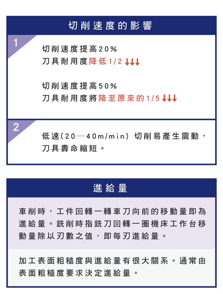
Higher speed raises friction heat, tool temperature and wear, so life falls — and not linearly: a small speed rise cuts life sharply. But too low a speed (about 20–40 m/min) invites built-up edge (BUE) and vibration, worsening surface and life. So pick a suitable speed band by material and avoid both extremes.
| Speed change (coated carbide, reference) | Tool life trend |
|---|---|
| Speed +20% | Life drops about half (1/2) |
| Speed +50% | Life drops to about 1/5 |
4. Feed vs Surface Roughness and Quality
Feed (f) is given in mm/rev. Surface roughness (Ra) is strongly tied to feed and affected by nose radius; in finishing, lowering the feed is the most direct way to control finish — but rather than a fixed limit, work the feed back from the target Ra and the nose radius; see Turning Machining Formulas: Speed, Feed & Surface Roughness.
| Feed | Effect |
|---|---|
| High feed | Rougher surface, high efficiency (roughing) |
| Low feed | Finer surface, lower efficiency (finishing) |
5. Depth of Cut (ap), Force and Machine Load
A larger depth means higher cutting force and machine load but greater removal per pass and higher efficiency; too large a depth or insufficient machine rigidity brings vibration and dimensional error. As a rule, roughing uses a larger ap for removal rate, while finishing uses a smaller ap with low feed for dimension and finish.
6. Material Characteristics and Recommended Parameters
The table gives reference ranges for coated carbide tools; actual values vary with grade, coating, cooling and machine rigidity, so follow the tool maker's recommendation.
| ISO group | Material | Vc (m/min) | f (mm/rev) | ap (mm) | Note |
|---|---|---|---|---|---|
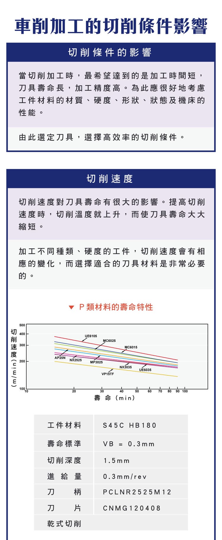
| P (steel) | Carbon steel S45C, alloy steel | 150–250 | 0.1–0.4 | 0.5–4 | Stable; use medium speed and steady feed; life drops fast if speed too high |
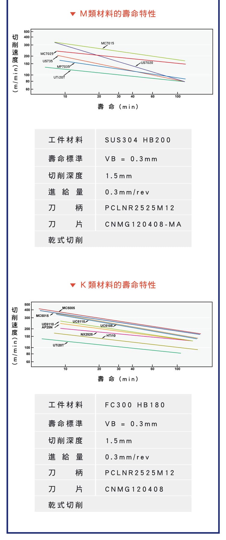
| M (stainless) | Austenitic SUS304 | 100–180 | 0.1–0.3 | 0.5–3 | Work-hardens with fast wear; lower speed, don't pause mid-cut, use a wear-resistant coated grade |
| K (cast iron) | Grey iron FC300 | 100–200 | 0.1–0.5 | 0.5–4 | Brittle chips, relatively stable cutting; manage evacuation and dust |
7. Test Conditions for the Tool Life Curves
The table gives the standard test conditions for the tool life curves (life judged at flank wear VB = 0.3 mm, dry cutting); follow each brand's catalog when selecting the actual insert grade.
| ISO group | Material | Hardness | ap | f | Holder | Insert |
|---|---|---|---|---|---|---|
| P (steel) | S45C | HB180 | 1.5 mm | 0.3 mm/rev | PCLNR2525M12 | CNMG120408 |
| M (stainless) | SUS304 | HB200 | 1.5 mm | 0.3 mm/rev | PCLNR2525M12 | CNMG120408 |
| K (cast iron) | FC300 | HB180 | 1.5 mm | 0.3 mm/rev | PCLNR2525M12 | CNMG120408 |
8. Tool life Criterion and Optimization
Industry commonly uses flank wear VB = 0.3 mm as the end-of-life criterion. To optimize: avoid the rapid wear from too high a speed, match grade and coating to the material (carbide, coated, ceramic, cermet), use coolant to control temperature, and monitor vibration to adjust in time. For wear patterns, see the Tool Wear Guide.
9. Common Turning Problems and Fixes
| Problem | Main cause | Fix |
|---|---|---|
| Tool life too short | Speed too high | Reduce speed, use a heat-resistant coated grade |
| Vibration | Speed too low (20–40 m/min) or low rigidity | Raise speed, increase clamping rigidity |
| Rough surface | Feed too high | Reduce feed; in finishing, work it back from the target Ra and nose radius |
| Low efficiency | Conditions too conservative | Moderately raise feed and depth |
| Stainless hard to cut | Work hardening | Lower speed, don't pause, use wear-resistant coated grade |
10. Optimization Summary
Cutting speed (Vc) is the key driver of tool life, feed (f) governs surface roughness, and depth (ap) affects force and load. Match grade and coating to the material class (P/M/K), control temperature and vibration, and the result is higher output, longer tool life and lower consumable cost. For spindle-speed and feed rate conversion, see the Turning Machining Formulas.
FAQ
How does cutting speed affect tool life, and how is end-of-life judged?
For coated carbide, +20% speed roughly halves tool life, and +50% drops it to about 1/5. Speed is the key driver of life, so choose the best speed for the material and avoid running too high. Industry commonly uses flank wear VB = 0.3 mm as the end-of-life point. Beyond it, accuracy and surface quality drop clearly, so the tool should be replaced or reground.
How do I convert spindle speed from cutting speed?
n (rpm) = 1000 × Vc ÷ (π × D), where Vc is cutting speed (m/min) and D is workpiece diameter (mm). For Vc=150 and D=50mm, n ≈ 955 rpm. Feed rate F (mm/min) = feed f × spindle speed n.
What to watch when turning stainless?
Stainless (M group, e.g. SUS304) work-hardens and wears tools fast. Lower the speed, use a wear-resistant coated grade, and avoid pausing mid-cut so the surface doesn't harden and make later cuts harder.
How do I improve surface roughness?
Roughness is mainly driven by feed. In finishing, lower the feed (work it back from the target Ra and the nose radius), keep a suitable nose radius, hold a stable speed and avoid vibration to improve the surface effectively.
For the full reading guides on this topic, see Surface Finish: A Complete Reading Guide, Tool Life and Wear: A Complete Reading Guide, Insert Selection: A Complete Reading Guide and Machining Calculation Reading Guide.
For the full reading guide on this topic, see Turning: The Complete Guide.
Published: 2026-03-24 | Last updated: 2026-10-20









