
Surface Grinders Only Grind Flat: Holding and Aligning Vertical and Angled Faces
The wheel on a surface grinder only travels horizontally, so the machine can only grind the face that points up. To grind a face perpendicular to the datum, or a face at an angle, the answer is not in the grinding parameters but in bringing that face to horizontal first. This article covers four things: which of the four fixtures to pick, the three shim alignment methods when you have none, how to calculate the gauge block stack for an angled face, and what will go wrong on a magnetic chuck if you skip the basics.
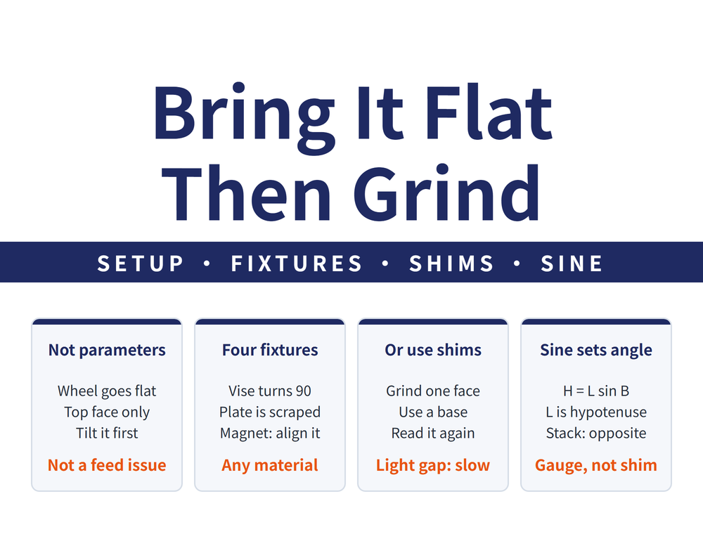
1. You change the setup, not the parameters
If the first thought when grinding a vertical or angled face is to change the feed or the wheel, the direction is already wrong. The wheel on a surface grinder travels horizontally, so the only face it can reach is the one pointing up. The problem therefore becomes one sentence:
How do you bring the face you want to grind to horizontal, and do it accurately? That accuracy decides whether the finished perpendicularity or angle passes. It is purely a work holding and alignment question.
Pick the method from part shape, size, accuracy requirement and batch size. For ordinary horizontal face work holding and grinding parameters, see Cylindrical, Internal and Surface Grinding: Workholding, Motions and Grinding Data. This article covers only vertical and angled faces.
2. With a fixture: choosing among four
| Fixture | How it is used | When to pick it |
|---|---|---|
| Precision vise | Grind face one on the base, then turn vise and part 90° and grind face two on the side | Small, non-magnetic parts; reaches 90 deg plus or minus 30 sec |
| Precision angle plate | Datum face against the vertical face, clamped with strap and screw, dialled in | High perpendicularity; common in tool and fixture making |
| Magnetic angle plate | Sits on the chuck; the brass strip must line up with the chuck insulation | Long and narrow parts |
| Precision V block | Part held in the vee by a yoke and clamping screw | Ends of cylinders; keeps end square to the diameter |
The two working faces of a precision angle plate are hand scraped, with perpendicularity error around 0.005mm. That is why it costs more than the other three, and why it can meet a high perpendicularity requirement. The line about lining the brass strip up with the insulation is not a fitting tip, it is the precondition for the plate holding at all: out of line, the flux does not cross, and the part is merely sitting there.
3. Without a fixture: grind one face first, then align
With none of the four to hand the approach is the same: finish grind one face of the part, use it as the datum, and align the face to be ground to horizontal by shimming under the part. The three methods differ in where the reading comes from.
| Method | How you read it | Verdict |
|---|---|---|
| Indicator on the head | Indicator on the ground face, raise and lower the head, compare | Needs a head you can mount to |
| Cylindrical square, light gap | Gap low, shim the left end; gap high, shim the right end | Hard to control, and slow |
| Dedicated indicator base | Read the cylindrical square first as datum, then read the part | Gives numbers, error is controllable |
How to shim with the third: if the reading on the part is larger than on the square, shim the right end of the part base, and pick shim thickness from the size of the difference. When reading the square, keep the indicator tip and the base locating point on the same vertical line, or you are measuring an error you created yourself.
4. Two practical details about shimming
The first is re-checking: always read it again after shimming. Shim the wrong way and the reading gets worse, and that looks exactly the same as not having shimmed enough, so you keep adding shim in the wrong direction.
The second is a shortcut worth knowing: if the part already has two ground parallel faces, you do not need a fresh datum. Read both, shim until the readings match, then grind the top face. Perpendicularity of the top face to both can reach within 0.01mm.
5. Angled faces: stack height H = L x sin B
An angled face on a surface grinder means tilting the part and then grinding it like any flat face. The hard part is not the grinding, it is tilting accurately. Tilt is expressed as either slope or angle, related by s = tan B, where slope s = (large end height H minus small end height h) divided by face length L.
Gauge block stack height H = L x sin B (L = centre distance of the sine cylinders, B = part angle).
That is the whole principle of a sine bar: the centre distance is the hypotenuse, the block stack is the opposite side.
| Condition | Stack height |
|---|---|
| Angle 30 deg, centre distance 200mm | 200 x sin30 = 100mm |
| Angle 20 deg 15 min, centre distance 200mm | 200 x sin20 deg 15 min = 69.224mm |
Both worked examples are transcribed from the technical source and have not been re-derived here. Check your angle units and centre distance before applying them.
6. Four ways to hold an angled face (the first three are sine methods)
| Method | Scope and limits |
|---|---|
| Sine magnetic chuck | Flat parts; maximum tilt 45 deg; lock screws must be fully tight |
| Sine precision vise | Small or non-magnetic parts; lock the sine bar before grinding |
| Sine bar plus angle plate | Raise the sine bar so the face being ground sits above the plate; remove every block once set |
| Magnetic V block | Faces at 90 deg; base angle often made 15, 30 or 45 deg |
With the third method, remove every block once the angle is locked, then load the part. The reason is a practical inference: the angle is already locked by the plate, so the blocks are the tool that measured the angle, not a support carrying grinding force. Leaving them in is using a gauge as a fixture. Thick parts can be held straight on the magnetic V block; thin or non-magnetic parts go in a precision vise first, and the vise is held by the block.
7. The magnetic chuck: seven things
Nearly every fixture for vertical and angled faces sits on the magnetic chuck. Neglect the chuck and none of the accuracy above is available.
| Item | What to do |
|---|---|
| Supply | Must be DC; the rectifier has to be working properly |
| Table | Clear swarf and dirt; wipe dry after work so fluid stays out |
| Residual magnetism | Magnetism remains after power off; use the demagnetise position |
| Removing parts | Never pull hard; break it loose with wood or brass, pad the wrench |
| Placement | Cover as many insulation strips as possible; thin parts in the middle |
| Position | The centre wears; grind close-tolerance small parts at the ends |
| Regrinding the table | Grind it energised, until sparking stops; do it as rarely as possible |
Rows four and seven can be read together: pulling parts off hard scores the table; a heavily scratched table, or one that is no longer flat, has to be reground, and regrinding should be kept as rare as possible to extend chuck life. Put together (a practical inference): break a part loose before lifting it, and the table scores less and needs regrinding less.
8. Stops: too little hold means a burst wheel
Small thin parts need stops left and right to keep them from shifting. Tall parts with a narrow base need larger blocks all round, and those blocks must sit slightly lower than the part.
The blocks are there to prevent an accident: with insufficient holding force the part tips over and the wheel bursts.
For wheel strength, imbalance and pre-mount checks, see Why Grinding Wheels Burst: Strength, Unbalance and the Checks Before Mounting. Thin parts distorting once clamped is a separate subject - not weak holding but a soft part - and is covered in Thin Parts Bow After Grinding: Separate Thermal Distortion from Clamping Distortion.
9. Frequently Asked Questions (FAQ)
Q: Perpendicularity is out of tolerance. What do I check first?
Check work holding and alignment before the wheel or the parameters. A surface grinder always grinds the face pointing up, so perpendicularity is decided by whether that face was brought to horizontal. With an angle plate, confirm it was dialled in. With shims, confirm you re-checked after shimming.
Q: Which fixture for a vertical face on a small non-magnetic part?
A precision vise. Its sides and fixed jaw are square to its base, so you grind the first face with the base down, then turn vise and part 90 degrees and grind the second face with the side down. The part does not need to be magnetic. For angled faces use a sine precision vise, which is equally material independent.
Q: Do the gauge blocks stay in once the sine bar is set?
With the sine bar and angle plate method, remove every block after the angle is locked to the plate, then load the part. The reason is a practical inference: the blocks are the tool that measured the angle, not a support carrying grinding force. On a sine magnetic chuck or sine vise the blocks are part of the fixture structure, so follow that fixture instead.
Q: The part is not holding well. Can I raise the current?
Check three things first: swarf on the table, whether the part covers enough insulation strips, and whether it sits on the worn centre area of the chuck. A tall part with a narrow base is meant to be supported by blocks all round and cannot rely on holding force alone, because too little hold tips the part and bursts the wheel.
Machine error shows up directly as part defects; for accuracy checks and the four acceptance items on a new machine, see Grinding Machine Accuracy: Error-to-Defect Map and the Four Acceptance Tests.
This article is part of Grinding Wheels and Machines: The Complete Guide - Reading the Wheel, Mounting It, Dressing It, and Tracing Defects; that guide shows how the whole topic fits together.
Published: 2026-09-19|Last updated: 2026-10-24









