
Insert Angle Guide: Negative, 7° & 11° Positive Inserts
Insert geometry (negative, 7° and 11° positive) plays a critical role in CNC turning performance and tool life. Negative inserts suit heavy cutting; positive inserts suit light cutting and finishing. Using the ISO groups (P, M, K, N, S) and brand chipbreaker cross-reference, you can quickly find the best insert setup for stability and efficiency.
1. What Is Insert Angle
Insert angle here means the insert’s own clearance angle; inserts are mainly divided into negative and positive. A negative insert (ISO 1832 2nd-position code N) has sides square to its base, i.e. 0° clearance, and sits in the holder at a negative rake angle, which is also why both faces can be used. A positive insert has sides inclined to its base, so it carries its own clearance, commonly 7° (C) or 11° (P). Different angles map to different cutting forces, edge strength and surface quality.
Positive or negative is a choice within indexable inserts; if you have not yet settled which kind of turning tool you need, start with Types of Turning Tools.
2. Negative Insert
Negative inserts have a strong edge and high impact resistance, and are usually double-sided and economical — suited to heavy cutting, high-load work, and cast iron and steel.
| Item | Content |
|---|---|
| Traits | Strong edge, impact resistant, double-sided |
| Applications | Heavy cutting, high load, cast iron & steel |
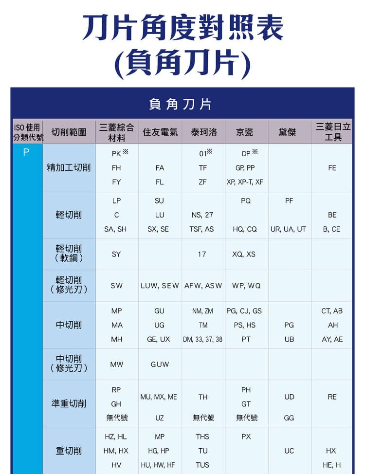
Common chipbreaker codes (maker examples; refer to each brand's own catalog):
| Use | Chipbreaker code |
|---|---|
| Medium cutting | MP, MA, MH |
| Heavy cutting | HM, HX, HV |
3. 7° Positive Insert
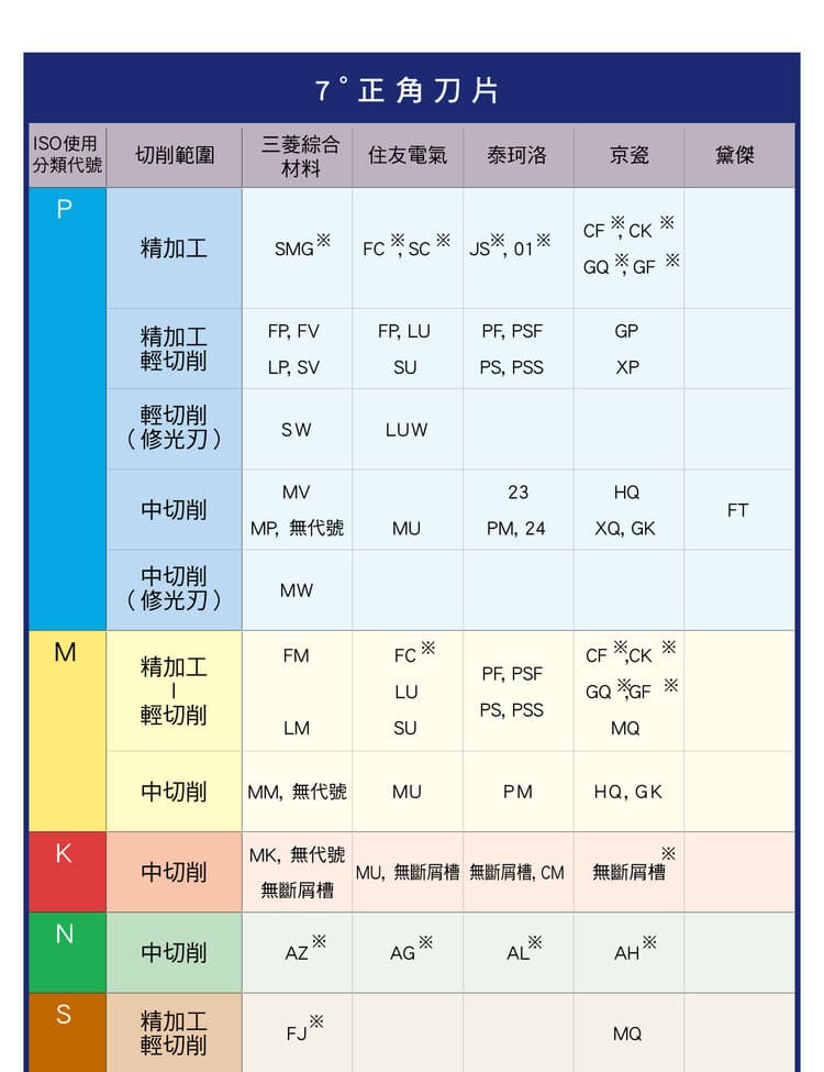
The 7° positive insert has low cutting resistance and cuts lightly, suiting low-to-medium loads such as finishing, light cutting and thin-wall parts.
| Item | Content |
|---|---|
| Traits | Low resistance, light cut, low-medium load |
| Applications | Finishing, light cutting, thin-wall parts |
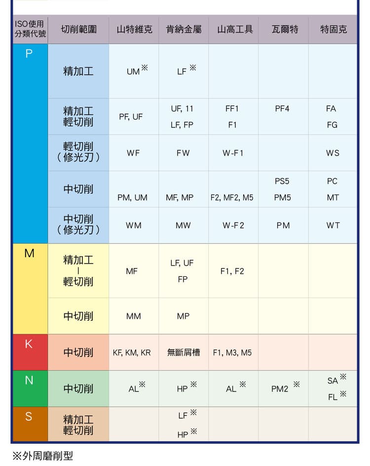
Common chipbreaker codes (maker examples; refer to each brand's own catalog):
| Use | Chipbreaker code |
|---|---|
| Finishing | SMG, CF, CK |
| Light cutting | FP, PF, GP |
4. 11° Positive Insert
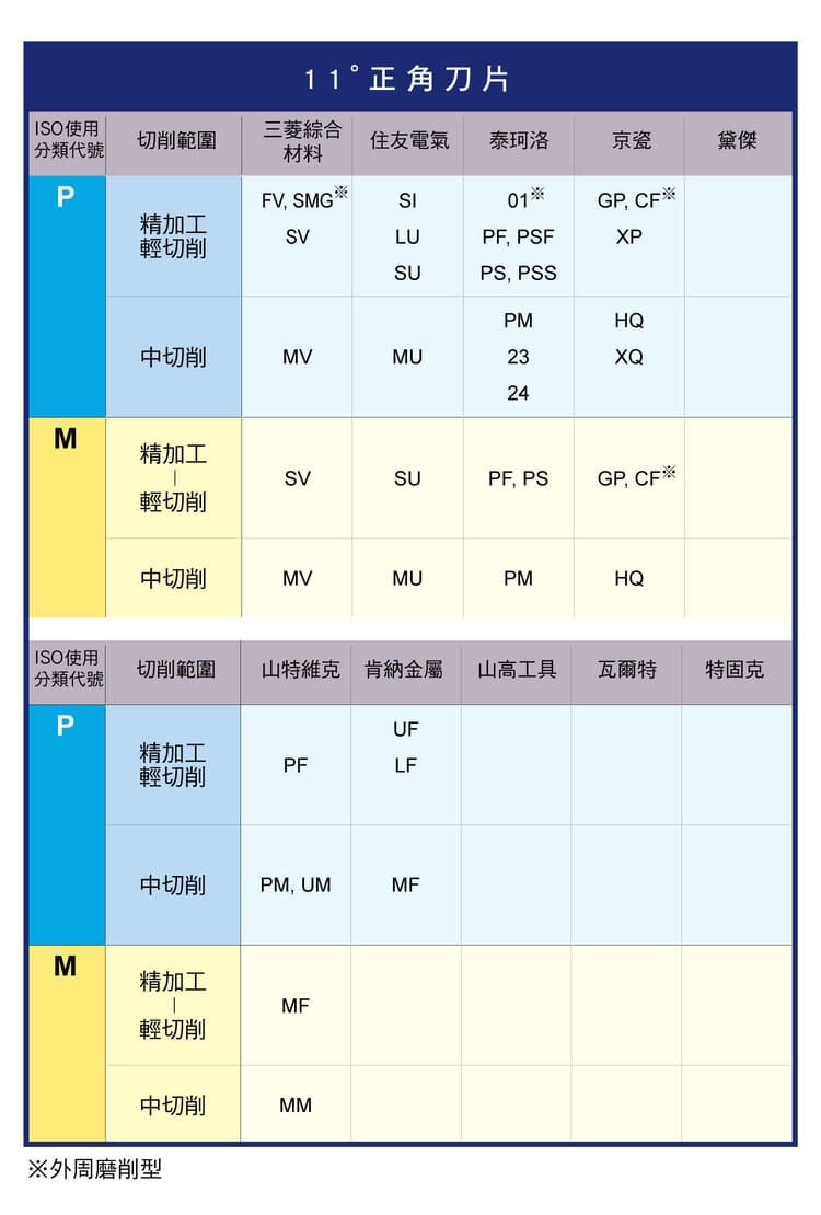
The 11° positive insert is sharper than 7° with even lower cutting force and the best surface finish, suiting super-finishing and stainless steel and aluminum work.
| Item | Content |
|---|---|
| Traits | Sharper than 7°, lower cutting force, best surface finish |
| Applications | Super-finishing, stainless steel & aluminum |
Common chipbreaker codes (maker examples; refer to each brand's own catalog):
| Use | Chipbreaker code |
|---|---|
| Finishing | FV, SV, SI |
| Light cutting | MV, MU |
5. ISO Classification and Angle Choice
By ISO workpiece group (P, M, K, N, S), the angle-selection principles are:
| ISO group | Angle guideline |
|---|---|
| P (steel) | Roughing → negative; finishing → positive |
| M (stainless) | Positive, to reduce work hardening |
| K (cast iron) | Negative first, for wear resistance |
| N (non-ferrous) | Positive, for surface quality |
| S (heat-resistant) | Positive or dedicated inserts, anti thermal crack |
6. Chipbreaker Pairing Logic
Match the chipbreaker to feed and depth of cut. Finishing uses low feed and a fine chipbreaker; medium cutting uses a general chipbreaker; heavy cutting uses a strong chipbreaker or none.
| Operation | Chipbreaker |
|---|---|
| Finishing | Low feed, fine chipbreaker |
| Medium cutting | General chipbreaker |
| Heavy cutting | Strong chipbreaker or none |
7. Insert Angle Selection Guide
Putting it together, the insert-angle guide by operation is below. Calculate actual cutting speed and feed from your material and machine conditions — see Turning Machining Formulas; for rake and clearance angle theory see Turning Tool Rake & Clearance Angles Explained.
| Operation | Suggested angle |
|---|---|
| Heavy cutting | Negative insert |
| General machining | 7° positive |
| High-accuracy machining | 11° positive |
| Thin parts | Positive insert |
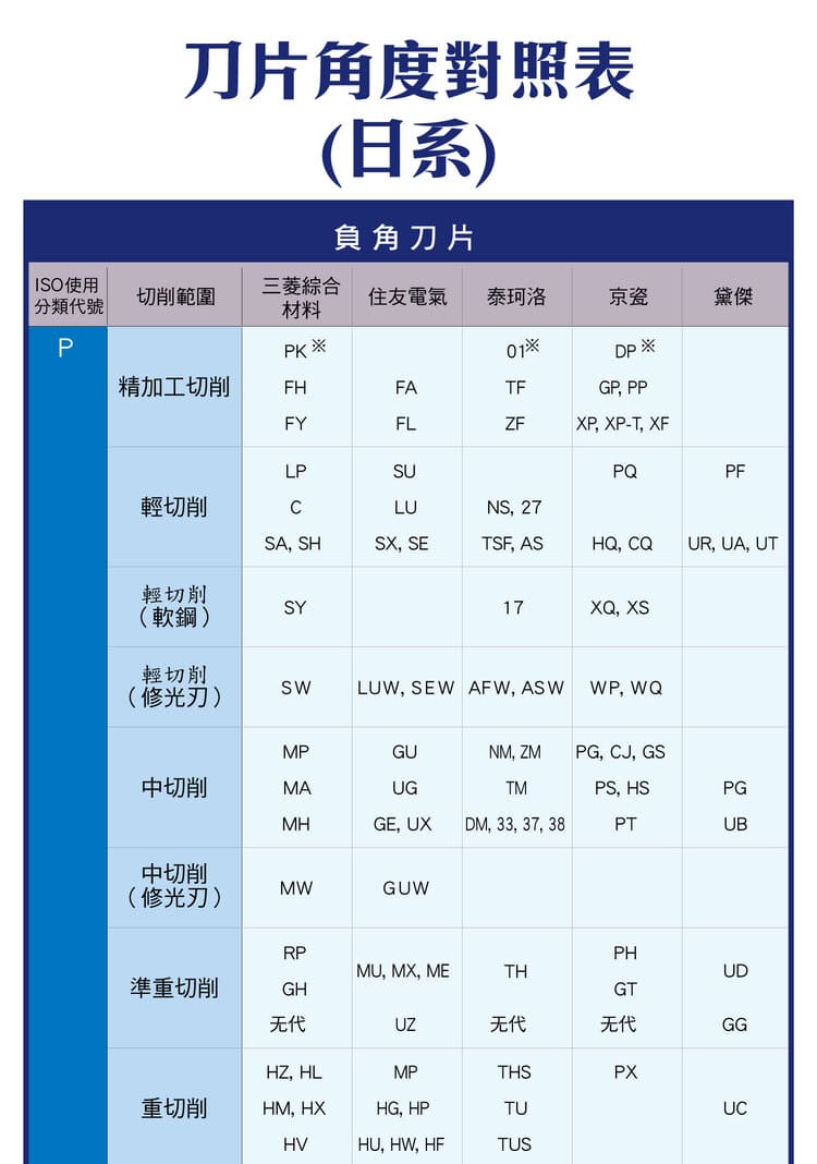
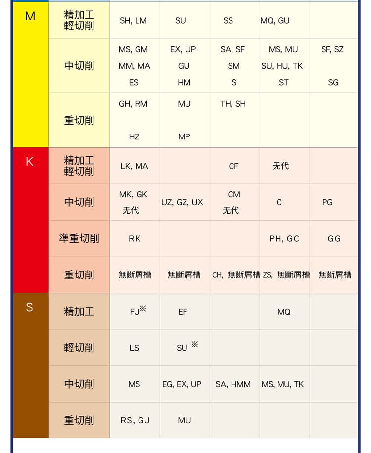
8. Cross-Brand Chipbreaker Code Cross-Reference (Negative Inserts)
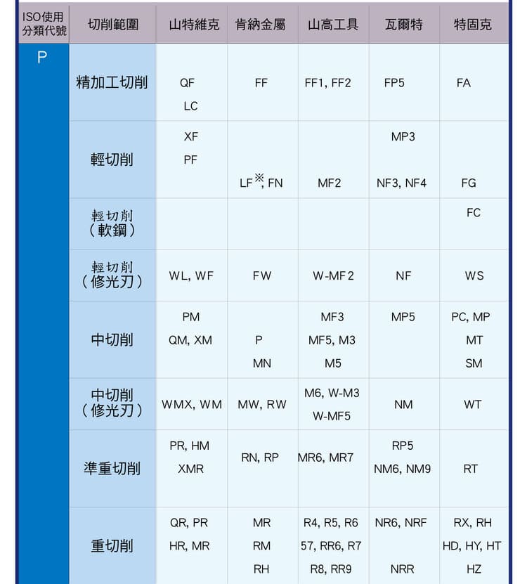
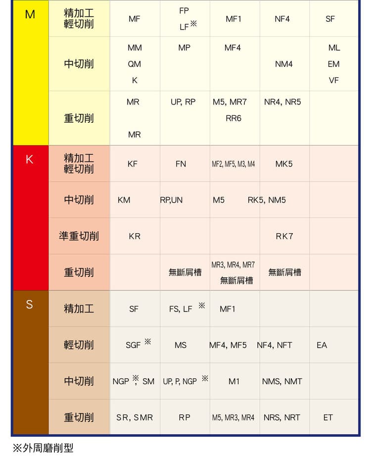
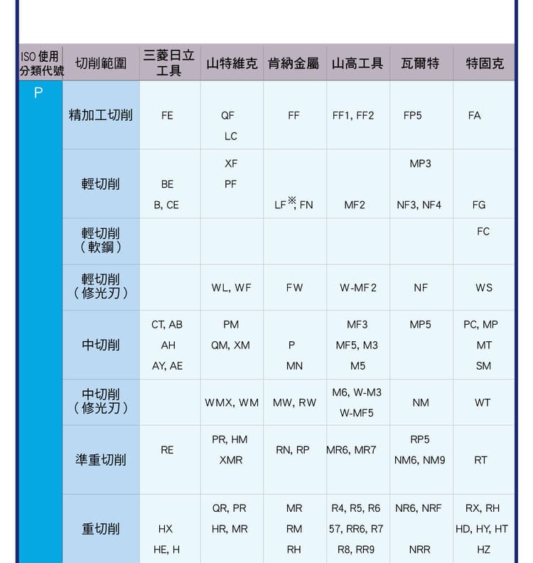
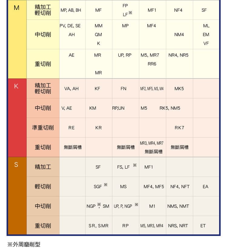
The charts below organize common negative-insert chipbreaker codes by ISO workpiece group (P/M/K/S) and by operation (finishing, light cutting, medium cutting, semi-heavy cutting, heavy cutting). First comparison set: Mitsubishi Materials, Sumitomo Electric, Tungaloy, Kyocera, Dijet, MOLDINO (Mitsubishi Hitachi Tool). Second comparison set: MOLDINO (Mitsubishi Hitachi Tool), Sandvik, Kennametal, Seco Tools, Walter, TaeguTec.
Note: this cross-reference is not an officially endorsed equivalence from any of these brands. Use it only as a conceptual aid when selecting inserts; for actual purchasing and substitution, always follow each brand's own catalog.
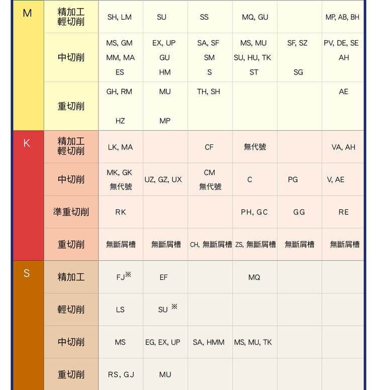
Second comparison set:
FAQ
Q: Negative vs positive insert — what's the difference?
Negative inserts have a strong, impact-resistant, usually double-sided edge for heavy cutting and cast iron/steel; positive inserts have low resistance, cut lightly and give a good finish for finishing, light cutting and thin-wall parts.
Q: How do I choose 7° vs 11° positive?
7° positive suits general finishing and light cutting; 11° positive is sharper with lower cutting force and the best finish, suiting super-finishing and materials such as stainless steel and aluminum.
Q: How do angles pair with ISO material groups?
P steel: negative for roughing, positive for finishing; M stainless: positive to reduce work hardening; K cast iron: negative first for wear resistance; N non-ferrous: positive for surface quality; S heat-resistant: positive or dedicated inserts.
Q: Can chipbreaker codes be used across brands?
Not recommended. The codes shown (MP, SMG, FV, etc.) are maker examples; naming and application ranges differ by brand, so select according to each brand's own catalog.
Published: 2026-07-23 | Last updated: 2026-10-20
For the full reading guides on this topic, see Insert Selection: A Complete Reading Guide and Chip Control: A Complete Reading Guide.
For the full reading guide on this topic, see Turning: The Complete Guide.









