
Tool Geometry for Dry Cutting: Three Design Rules, Edge Reinforcement and the Rake Face Land
With no cutting fluid to carry heat away, the geometry has to carry it instead. This article covers the three design rules for dry cutting tools, three ways of reinforcing the edge, why a rake face land drops the temperature so sharply, and what brittle tool materials, dry tapping and the heat-removing structures each require.
1. Three design rules: make less heat first
With no cutting fluid there is no external route for the heat. So dry cutting tool design does not start from "how to cool it" but from how to generate less heat and how to send what there is out with the chip:
| Rule | What it means in the design |
|---|---|
| Heat dissipation is the core problem | Aim the structure at low cutting force and low friction, cutting the heat at source |
| Deep holes need evacuation first | A purpose-built dry deep-hole drill with a large helix and a high-cobalt micrograin carbide reaches 7 to 8 times diameter with no fluid |
| Design for low cutting force | A larger rake angle with a suitable edge form, such as a narrower web and a larger back taper to cut friction |
Geometry optimisation runs in two directions: 1 reduce the contact area between tool and workpiece (a larger back taper and helix on a drill, for instance) and 2 maximise surface lubricity and prevent built-up edge. One constraint to keep in view: cermet, ceramic, CBN and PCBN are all far more brittle than carbide, so support has to be reinforced and pressure spread. On material choice see choosing tool materials for dry cutting.
2. The price of a large rake angle: reinforcing the edge
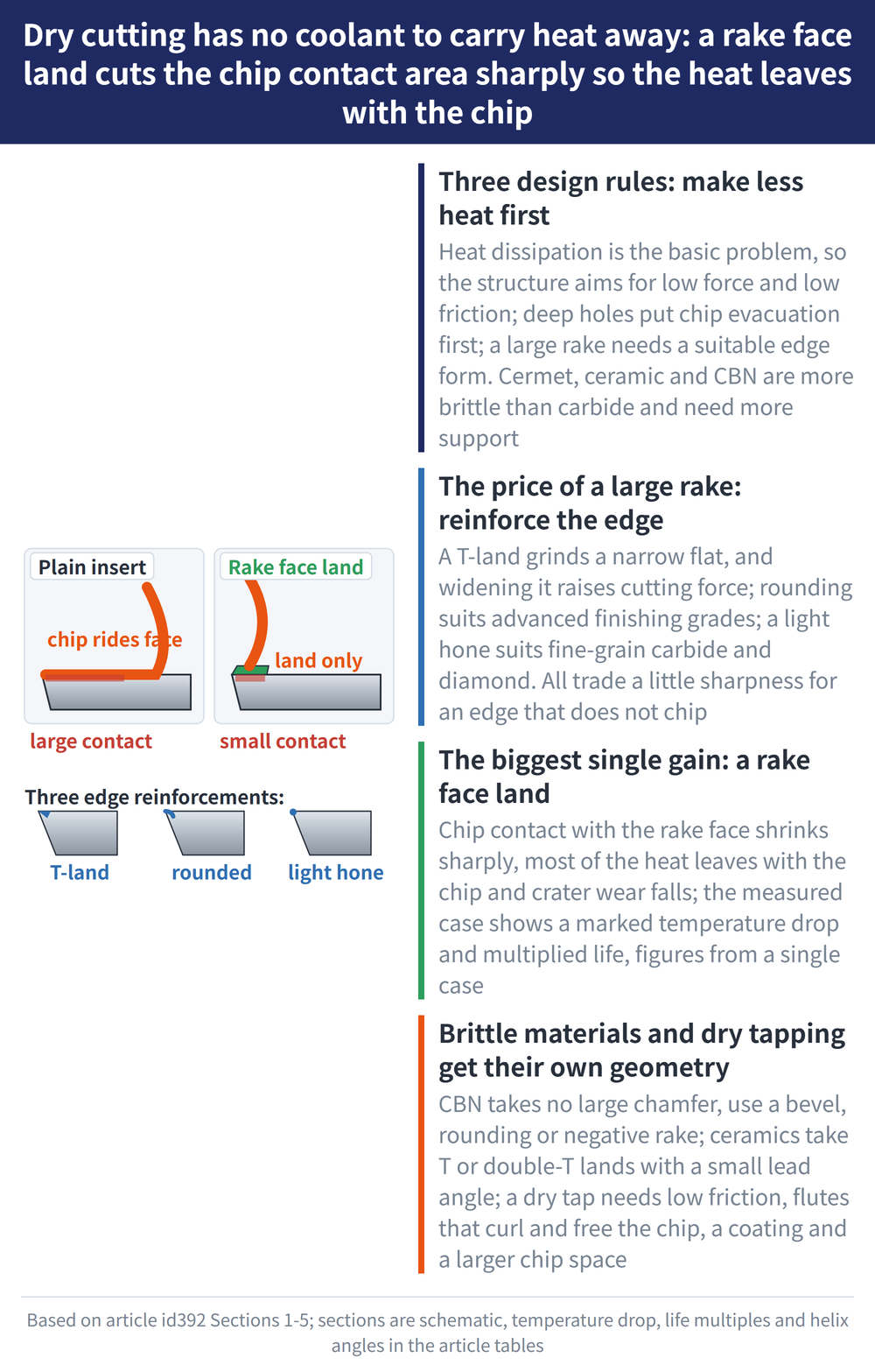
Section 1 calls for a large rake angle, but a large rake weakens the edge. Three reinforcement methods each have their place, and stronger is not automatically better:
| Method | How it works and where it fits |
|---|---|
| T-land (chamfer) | A narrow flat ground on the edge in place of the fragile sharp edge. The work is finding the best width and angle — increasing either raises cutting force |
| Honing | Rounds the sharp edge without the corners of a T-land. Suits advanced insert materials used for finishing, with a small depth of cut and light feed |
| Light blunting | For fine-grain premium carbide and diamond tools, relying on substrate strength to stay sharp, which lowers temperature and holds tool life |
All three share one logic: give up a controlled amount of sharpness so the edge does not chip. On edge preparation generally see how edge rounding affects coating adhesion and tool life.
3. The biggest single gain: a rake face land
In turning and milling the chip contacts a large area of the rake face, heat accumulates and crater wear follows. With a land on the rake face the contact area drops sharply and most of the heat leaves with the chip. The measured case gives these effects:
| Item | Measured case effect |
|---|---|
| Cutting temperature | About 400°C lower than a plain insert |
| Shear angle | Increased |
| Tool life | 3 to 4 times longer at normal cutting speed, or trade the margin for higher speed and output |
A related approach is controlling where the chip goes: some indexable inserts form a scaled contact face that bends the chip sideways so its exit direction is controlled, which matters in dry cutting because no fluid is there to flush it. The multiples and temperature difference above are single measured cases, not general specifications.
4. Brittle materials need their own geometry
Ceramic and CBN are brittle, so their geometry does not follow carbide practice:
| Material | Geometry direction |
|---|---|
| Ceramic | A single or double T-land, with a small lead angle where possible; usual insert shapes are square, triangular and 80° rhombic |
| CBN | Keep the chamfer small — on hardened steel the contact runs hot enough that a large chamfer wears the edge quickly. Use a bevel or radius and a negative rake instead |
A PCBN dry-cutting tool for large chill-cast rolls serves as a structural example. Its four features are a negative inclination angle so the edge enters progressively rather than all at once (lower impact, less prone to vibration), a larger lead angle with a transition edge, a wiper edge to hold surface finish as feed rises, and a small clearance angle for edge strength. Tool life in that case is 50 to 100 times that of a carbide tool. ⚠ The full cutting data combination for that case is a single-specification measured value and is not reproduced here; only the multiple and the structural logic are kept. Ask the tool supplier for specific figures if you need them.
5. Dry tapping: what the tap has to look like
Tapping is an enclosed operation, which makes it the hardest case for dry cutting. Tap design has to cover four things: 1 low friction; 2 a flute form that curls the chip and lets it leave the hole freely; 3 a surface coating, commonly TiN or TiCN; 4 more chip space and a larger back taper.
| Case | Flute form and helix |
|---|---|
| Steel, blind hole | Commonly a 35° high helix |
| Steel, depth over 2x tap diameter | A low helix, typically 5°, with a chamfer length of 2 to 3 threads |
| Cast iron, through and blind alike | Straight flutes throughout, chamfer length also 2 to 3 threads |
Small diameter taps may take a special form for strength and rigidity, such as a fluteless forming tap, which suits small threads and more ductile materials. On whether dry tapping works at all see is dry tapping feasible.
6. Three structures that carry the heat away
Sections 1 to 5 are about making less heat. This one is about removing heat or chips structurally:
| Structure | Principle and reported effect |
|---|---|
| Heat pipe turning tool / face mill | Outwardly a normal tool, with a heat pipe formed inside the body or each tooth. Measured: 50 to 60°C lower, rake face average temperature two thirds of a plain tool, life up 2 to 3 times |
| Rotary turning tool | A round insert on bearings rotates during the cut, so the edge stays sharp throughout |
| Vacuum turning tool / milling cutter | Negative pressure at the cutting zone draws chips away through ducting. Chip recovery for the milling version reaches over 95% |
What the three share is that no external coolant has to be poured on, which suits CNC machines, machining centres and automated lines. These figures are likewise reported measured cases, not general specifications.
7. Frequently asked questions
Q: Is a more heat resistant tool all that dry cutting needs?
Heat resistance is the material side; the geometry side works differently. The first design rule is heat dissipation, and the way it is addressed is by lowering cutting force and friction first, so less heat is generated, and then letting what remains leave with the chip. That is why you see large rake angles, reduced tool and workpiece contact area, and larger back taper and helix on drills. Swapping to a more heat resistant grade without touching geometry generates the same heat; the tool simply survives it a little longer.
Q: A larger rake angle and a reinforced edge sound contradictory.
They are two ends of one trade-off. A large rake lowers cutting force and heat but weakens the edge, so strength is added back in a controlled way. A T-land grinds a narrow flat, and since widening it or steepening it raises cutting force the job is finding the optimum. Honing suits advanced insert materials in finishing, with light depth of cut and feed. Light blunting is used on fine-grain premium carbide and diamond tools. All three trade a little sharpness for an edge that does not chip; they differ in how the sharpness is traded and on which materials.
Q: Why can a CBN chamfer not be enlarged like other materials?
Because enlarging the chamfer enlarges the contact area, and CBN is generally used on hardened steel where the contact already runs hot. More contact pushes the temperature high enough to wear the edge quickly, so the reinforcement becomes an accelerant instead. CBN therefore avoids a large chamfer and takes its strength from a bevel or radius with a negative rake. Ceramic goes the other way, using a single or double T-land with as small a lead angle as the job allows.
Q: Can the multiples and temperature figures be used to estimate savings?
As a direction yes, as numbers no. About 400°C lower, three to four times the life, the PCBN case at 50 to 100 times, the heat pipe at 50 to 60°C and two to three times — all are single measured cases, and each depends on that case's workpiece, tool and conditions. This site also deliberately leaves out the full cutting data for those cases, because a single-specification measured value does not survive separation from its preconditions. For an investment case, use your own trial cutting data or verification supplied for your specific part.
This article is part of Tool Materials and Coatings: The Complete Guide - Separate Substrate From Coating, Then Work Back From the Workpiece; that guide shows how the whole topic fits together.
This article is part of Dry Machining: The Complete Guide - Losing the Coolant, and How Five Processes and Three Techniques Cope; that guide shows how the whole topic fits together.
Published: 2026-08-30|Last updated: 2026-08-30









