
Face Milling Tool Angles: Axial/Radial Rake, Lead Angle & Rake
In face milling, tool angles — axial rake (GAMP), radial rake (GAMF), lead/entering angle (KAPR), rake and inclination — directly affect cutting force, chip direction and tool life. The right combination raises efficiency, cuts vibration and improves finish. Understanding each angle and positive vs negative use is core to optimising milling and tool selection.
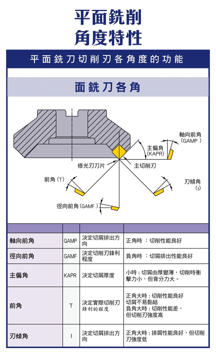
1. Main Face-Milling Tool Angles
| Angle | Function | Positive / negative trait |
|---|---|---|
| Axial rake GAMP | Sets chip-out direction, lowers resistance | Positive = better cutting / negative = stronger |
| Radial rake GAMF | Sets edge sharpness | Positive = free-cutting / negative = durable |
| Lead angle KAPR | Controls chip thickness and direction | Small = thinner chip / large = concentrated force |
| Rake (T) | Sets cutting sharpness | Positive = free, no BUE / negative = strong but high force |
| Inclination (I) | Controls chip direction and load | Positive = smooth chip flow / negative = stronger |
Tool angles set cutting-force direction, chip evacuation, tool life and finish — core to tool choice and conditions.
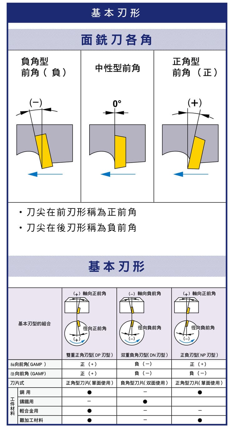
2. Basic Insert Geometry
| Type | Trait | Use |
|---|---|---|
| Negative | Strong, double-sided | Cast iron, heavy cuts, roughing |
| Neutral | 0°, balanced | General machining |
| Positive | Free-cutting, low force | Soft materials, aluminium, finishing |
3. Angle Selection and Strategy
Rule: for efficiency / light cutting → positive; for strength / heavy cuts → negative. Stable machining needs machine rigidity and less vibration; optimise chip flow by tuning axial and radial rake. In practice choose by material (cast iron leans negative, aluminium positive) and rough/finish need. For parameters see the Face Milling Formula Guide; for tool choice see the Face Milling Tool Selection Guide.
4. Engineering Priorities
The key is matching angle combination, workpiece material and cutting conditions. A sound choice raises efficiency, extends tool life and improves finish. Angles are part of the insert/cutter design — follow the maker's spec and suitable materials when selecting.
FAQ
Q: Positive or negative insert?
Positive is free-cutting with low force — good for soft materials (aluminium), thin parts and finishing; negative is stronger and double-sided — good for cast iron, heavy cuts and roughing. Choose by hardness and stability; lean positive when tooling is weak or vibration-prone.
Q: How do axial (GAMP) and radial (GAMF) rake differ?
Axial rake mainly sets the upward chip-out direction and resistance; radial rake mainly sets edge sharpness. Together they form the effective cutting angle, often combined as double-positive, double-negative or positive-negative to balance cutting and strength.
Q: How does the lead angle (KAPR) affect machining?
A smaller lead angle thins the chip and spreads the force — better for thin walls and interrupted cuts; a larger one (near 90°) concentrates radial force — good for square-shoulder facing. It also changes the axial/radial force split and load distribution.
Q: Still vibrating with the right angle?
Angle is only one factor. Vibration also depends on machine rigidity, tool overhang, clamping and speed. Shorten overhang, stiffen clamping, tune speed away from resonance and pair a positive insert to cut force. See the face-milling clamping guide.









